Interesting comments —
Bedini had an amp in the 80s that was constant voltage and the current varried with the music . He talks about it and shows it in one of his old youtube videos about the Bedini Linear Amplifier Regulator
In reality, a 300 watt audio output transformer with near-perfect fidelity from 50 Hz to 50 kHz will be massive, truly massive, and quite costly, if it is even possible to achieve at all. (50 kHz upper end needed to achieve at least fidelity at 3rd harmonic of your highest desired frequency (~6 kHz x2 x2 x2) for example.) Going down to 25 Hz will quadruple the size and cost beyond that. Going down to 12.5 Hz quadruple again, and so on. Do not waste your precious precious time … many smart minds at many companies over many decades have already pursued that elusive goal and achieved what is presently available. Connecting old Bell/WE transformers in new novel ways is likely to fail patent approval even after facing years of struggle against resistant examiners having unlimited budget and every reason to refuse (like the Very Strong motive to keep their jobs by rebuking old tech merely rearranged). No offense, but please please do not get side-tracked into the mire.
“But my point is: It’s not the tubes that sound better. It’s the tube circuit that sounds better.” — if that’s true, prove it easily — set up an audio output stage using high-voltage transistors and drive the primary of an an audio power output transformer off their high-impedance legs (collectors or drains depending upon device) — that tends to mimic the relatively high-impedances of power tubes’ plate outputs. The finding will almost certainly be that practically zero magic happens due to the transformer or in the magnetic domain — this has been deeply explored in “high-end” audio since way back. Tonal “magic” has been generally zeroed in as being due primarily to high-resistance parts in high-impedance circuitry adding “pleasing” 2nd-order harmonics via signal coherent/in-phase / locallized voltage sags. A perfect example of this: DUMBLE guitar amplifiers famously advantage this quirk of cascading the pre-amp stages after the main power tube rails.
Paul Carlson’s lab of Vancouver Canada on his Youtube channel had two 600 watt Audio Research Tube amplifiers he worked on. Schematics showed output transformer windings were like what’s in McIntosh Amplifiers.
The winding technique is called bi-filar.
“…the amplifiers that are in current use really not are not adapted to driving speakers…because the speakers … say that [they] have an 8 ohm characteristic impedance… but that’s that’s like a a nominal value. The impedance varies wide wildly. And, because all the amplifier designs are pretty much constant potential, that means that the power going into the speaker varies with frequency. So it screws your frequency response up and makes for you know like dead spots and the speaker kind of mucking the signal up because it’s not getting driven by the impedance that it wants at that frequency.
“This amplifier design is a constant wattage amplifier. So if the impedance of the speaker changes the amplifier works in a way such that it will try to maintain a constant power for for a given voltage at the input from whatever CD player or whatever you’re putting into it. It tends to want to deliver constant power.
“That’s one of the main reasons why vacuum tube amplifiers sound better than transistor amplifiers: Because the vacuum tube design (other than how it’s modified by feedback) but intrinsically it tends more for a constant wattage output. So if you use transistors and you made the same circuit configuration and all that, you could get similar results. But my point is: It’s not the tubes that sound better. It’s the tube circuit that sounds better.”
Transcript
Click to reveal
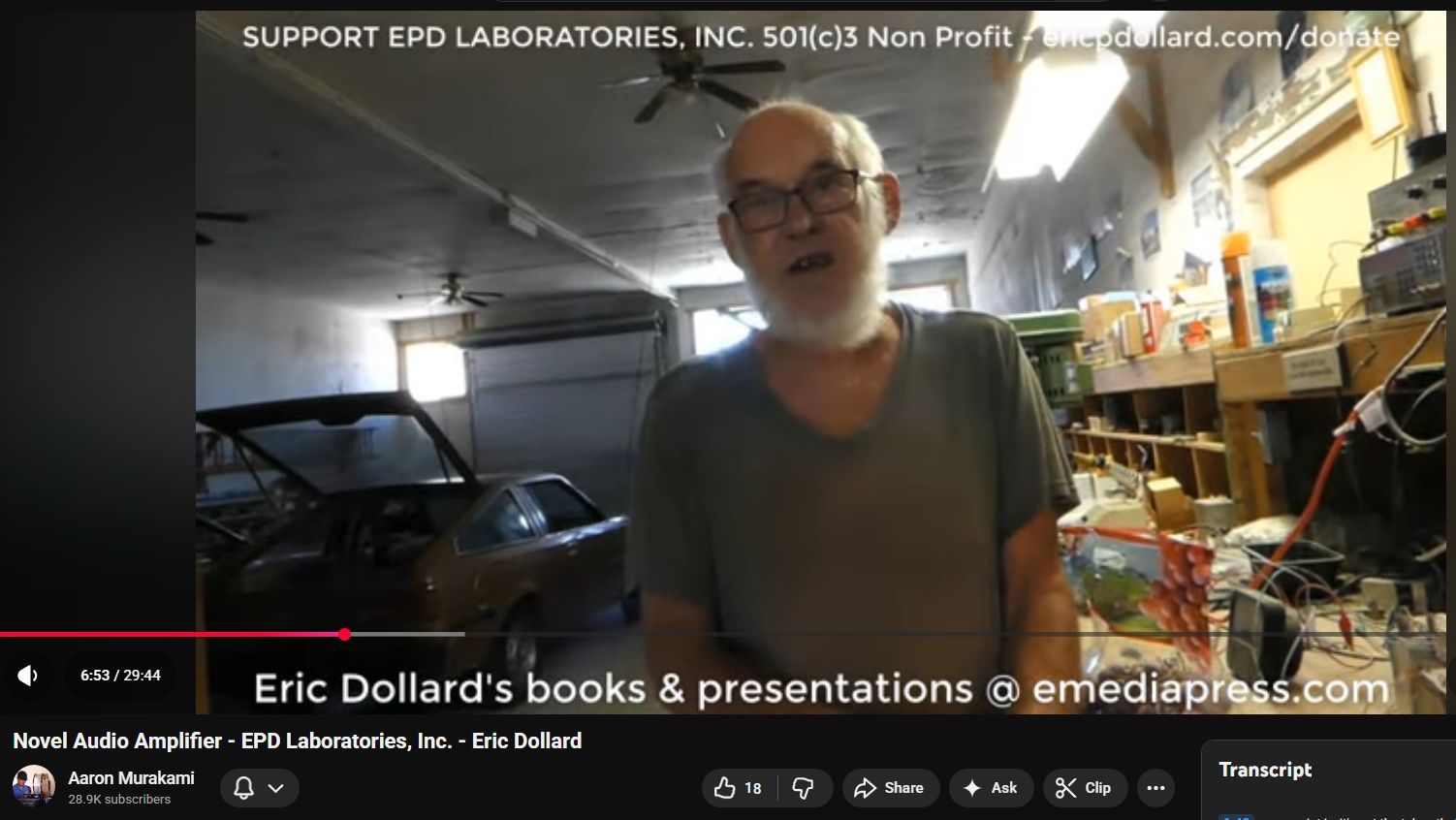
One of the things that I'm here for is
0:07
to work with Eric on this amplifier,
0:11
which is not the so-called commercial
0:13
one. This is to amplify the seismic
0:16
signals.
0:17
No, this is the
0:18
the
0:20
how would you say? This is the
0:23
the most complete form of the amplifier.
0:26
The full embodiment.
0:27
Yeah, full embodiment.
0:29
Okay. So, this is the one that we're
0:31
going to patent. Um, this this is just
0:34
for our own internal records, but
0:37
this is going to go in the cable TV
0:38
shack.
0:40
Okay.
0:40
So, this thing was intended to amplify
0:42
the earth signals.
0:44
So, is this going to amplify the the
0:48
signals coming off the long the long
0:50
line?
0:50
Yeah.
0:51
So,
0:52
so that this is this is basically the
0:54
line amplifier and then these are going
0:56
to be the input amplifiers. These are
0:58
already made.
1:02
So these go
1:03
So that's a previously manufactured
1:05
western electric.
1:07
Yeah. This these were a real
1:08
And what were those typically used for?
1:10
This was used in Korean War um army
1:15
frequency division multiplexing
1:18
equipment.
1:21
12 telephone channels on one pair of
1:23
wires.
1:26
And we went over a lot of the
1:27
multiplexing stuff in the musical
1:30
seismograph where we had
1:32
Yeah.
1:40
Okay. And so what's
1:44
kind of the overview of the novelty of
1:46
this particular full embodiment
1:50
uh amplifier? The tubes are not being
1:52
used for voltage gain
1:56
and like you said they just add power
1:57
and all
1:58
power gain. So basically this amplifier
2:01
you know looking at the diagram here is
2:03
a transmission line
2:06
made of a series of transformer windings
2:15
and then the tubes are part of the
2:17
transmission line. And you said the
2:20
tubes add power but all the
2:21
amplification is in the transformer.
2:23
Transformer the transformer windings.
2:25
That's that's that's what's doing the
2:26
voltage multiplication.
2:28
The tubes are basically just negative
2:30
transconductance devices. They just take
2:33
power from the power supply and deliver
2:35
it to the signal as the signal
2:37
propagates through this series of
2:39
transformer windings.
2:42
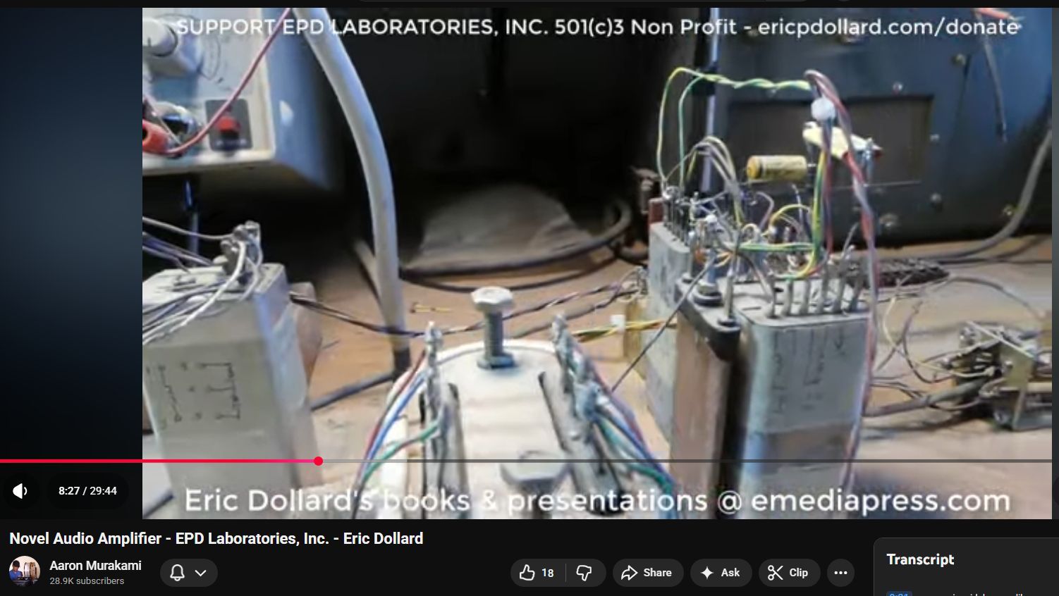
So you can see here there's a lot of you
2:45
know pretty heavy interconnection
2:47
between all these transformers
2:54
and those are not your ordinary
2:56
transformers. Those are the western
2:58
electric transformers from the Bell
3:00
system,
3:03
which are nearly impossible to find
3:05
anymore.
3:08
And if you do, they're very expensive.
3:13
Let that keep running for a second. I
3:16
get some little more light.
3:19
[Music]
3:31
So provisional needs to be filed on this
3:33
for
3:35
this can be scaled up. The idea I have
3:39
when I developed this at Landers
3:42
was to scale it up to a 300 W audio
3:45
amplifier.
3:45
Mhm. using uh the 811 and 812 vacuum
3:50
tubes which are still available.
3:56
They still make those. Not to say that
3:58
any of the stuff that's made is very
4:01
reliable or accurate, but
4:04
there's still enough surplus around.
4:09
So there's a there's a Macintosh version
4:11
and this would be like an advancement of
4:14
the Macintosh design.
4:16
Mhm.
4:17
So there's a there is a YouTube video.
4:21
I forget the title of it, but it's a
4:22
Macintosh 300 watt amplifier.
4:26
So that's kind of this advancement on
4:29
the Macintosh design. And that's u kind
4:32
of the end aim with this is to build a a
4:36
stereo 300 watt amplifier that's all
4:38
vacuum tube. So you said the um
4:42
Macintosh amps they brought it up to a
4:44
certain point
4:46
but they didn't actually take it all the
4:48
way where you have and where you've
4:51
taken it is um a new novel way to do it
4:56
that's patentable.
4:58
Yeah. Well, the whole the whole idea is
5:00
is this is the thing is is the
5:03
amplifiers that are in current use
5:05
really not are not adapted to driving
5:07
speakers.
5:08
Mhm. Okay.
5:09
Cuz the speakers don't have a you know
5:12
they can say that you have an 8 ohm
5:14
characteristic impedance speaker.
5:17
But that's that's like a a nominal
5:20
value. The impedance varies wide wildly.
5:23
And because all the amplifier designs
5:25
are pretty much constant potential,
5:29
that means that the power going into the
5:31
speaker varies with frequency. So it
5:33
screws your frequency response up and
5:36
makes for you know like dead spots and
5:39
uh you know the speaker kind of mucking
5:42
the signal up because it's not getting
5:44
driven by the impedance that it that it
5:46
wants at that frequency. This amplifier
5:49
design is a constant wattage amplifier.
5:54
So
5:55
if the impedance of the speaker changes
5:57
the amplifier works in a way such that
6:01
it will try to maintain a constant power
6:04
for for a given you know voltage at the
6:08
input from whatever you know CD player
6:11
or whatever you're putting into it. It
6:13
tends to want to deliver constant power.
6:15
That's the one one of the main reasons
6:16
why vacuum tube amplifiers sound better
6:18
than transistor amplifiers.
6:23
because the vacuum tube design other
6:26
than how it's modified by feedback but
6:29
in intrinsically
6:32
it tends more for a constant wattage
6:33
output.
6:36
So if you use transistors and you made
6:40
the same circuit configuration and all
6:42
that you you could get similar results.
6:45
But
6:48
my point is, it's not the tubes that
6:51
sound better. It's the tube circuit that
6:53
sounds better.
6:59
But in general, transistors do have a
7:02
funkier distortion and and it's a very
7:05
difficult distortion to get rid of.
7:08
So, how does this this one differ from
7:11
the one that we're going to um put into
7:14
commercial production?
7:15
The one we're putting in commercial is a
7:18
a simplified version of this.
7:20
Uh-huh.
7:22
It uses less transformers,
7:25
you know, and um
7:28
and transformers that that can be
7:30
readily manufactured or may already be
7:32
available. These type of transformers
7:34
here, I mean, you look at all the taps
7:35
on there.
7:36
Yeah.
7:37
You know, now I don't know if a
7:40
transformer company can duplicate those
7:42
or
7:46
but but at any rate if this thing is
7:48
scaled up then these transformers would
7:51
have to be scaled up which is possible
7:54
because their impedance you know and all
7:56
those things can be identified
7:58
then the transformer manufacturer can
8:00
just you know wind the transformers but
8:03
that but as you see you know it's not
8:04
just a you know primary secondary in a
8:07
simple form. There's all kinds of taps
8:09
involved on there.
8:13
And then there's certain networks that
8:15
that stabilize the uh
8:18
the frequency response for
8:21
non-scinosidal waves like square waves
8:23
or pulses or any of that type of stuff.
8:26
So this this was set up here to be an
8:29
amplifier for the the seismic
8:32
system.
8:33
Mhm.
8:35
So because the seismic system after it
8:38
goes through the modulator, the signal
8:40
is a square wave
8:42
and then the output modulator converts
8:45
that back into the steady state or you
8:48
know slow stuff is uh the amplifier has
8:51
to have excellent fidelity
8:53
characteristics and make sure that that
8:55
square wave goes all the way through
8:56
without any distortion. Otherwise when
8:58
the two modulators do you know their
9:00
conversion back and forth they'll get
9:02
you know inconsistencies in relationship
9:06
between the input and output. So the
9:09
commercial amp is it possible to make a
9:12
solid state version that's
9:15
you know it's not going to be as good
9:17
but for like a lower tier more easily
9:19
manufacturable
9:22
one incorporating the
9:24
possibly but but I don't know. Well, I
9:26
mean, that's what we're going through
9:27
now with these damn MOSFETs.
9:29
Yeah.
9:30
And obviously they're they seem to be
9:32
more trouble than they're worth.
9:34
So, like for the, you know, you're
9:36
you're building a radio frequency
9:38
amplifier for 50 watts driving a
9:41
moderate impedance load. It's actually a
9:43
lot simpler and more efficient to use
9:45
vacuum tubes.
9:47
Mhm. So in that case rather than the
9:49
MOSFETs there's tubes available that are
9:52
manufactured the 6L6 that would produce
9:55
that 50 watts and wouldn't need it uh
9:58
another stage of amplification to go
10:00
from the master oscillator. The 6L6s
10:04
would amplify it straight
10:06
but it would be it would be twice the
10:08
volume of the transistors. But the
10:10
problem is the transistors are too low
10:12
of an impedance to feed things like you
10:16
know what you're using is you know a
10:18
gaseous discharge tube which requires
10:20
like you know three 300 to 500 volts.
10:24
Mhm.
10:29
Is this related?
10:30
That's the these here.
10:32
Okay.
10:32
So these are the amplifiers for the um
10:35
the input to the uh toic receiving
10:38
equipment.
10:41
So one there's two types. One is uh an
10:44
input amplifier called the receiving
10:46
amplifier.
10:49
So
10:51
these uh will accept the western
10:53
electric tubes that have high voltage
10:55
filaments. So we can run the filaments
10:57
right off the plate supply. So there's
10:59
only one voltage
11:01
because the s the power to this has to
11:03
be phantom through a
11:06
um a neutralizing coil or a phantoming
11:09
coil. So you can only get one voltage.
11:13
So these tube filaments will be this
11:14
will be modified to hook the filaments
11:16
in series and then because the antenna
11:19
is a high impedance it will be delivered
11:23
to this point and the input transformer
11:26
will just be used as a uh an input choke
11:31
and then the output of this goes to the
11:33
input of the line amplifier and then
11:37
this sends a signal up to the shack.
11:39
[Music]
11:43
And in between the input amplifier and
11:45
the line amplifier is the um is the
11:48
network that uh takes the interference
11:52
out. So basically there'll be a lowass
11:55
filter.
11:56
So you can't hook the lowass filter to
11:59
an antenna and you can't hook it to a
12:00
transmission line because of the
12:02
interaction. So because these amplifiers
12:04
have a constant impedance,
12:07
then the filter will work perfectly in
12:09
between the two.
12:11
And because this is vacuum tube stuff,
12:13
it won't be damaged by, you know,
12:16
lightning discharges and things that
12:18
would screw the transistors up. The
12:20
front end has got to be vacuum tube.
12:23
And these are this is very high quality
12:25
and all made by Western Electric. I
12:28
mean, this you couldn't actually like
12:31
works of art.
12:32
They're beautiful inside.
12:36
So, basically, I got to get in there and
12:39
series the filaments. And then there I
12:42
have to take out this uh voltage
12:44
dropping resistor and that's no big
12:45
deal. I just jumper it. Then the
12:47
amplifier is modified.
12:50
So have to make a p make a panel and you
12:54
know fit the connectors and
12:57
put in the related compo components the
13:01
the current regulator for the filaments
13:04
and the phantom transformer and whatever
13:07
protective devices.
13:09
Okay.
13:15
Okay. This is a commercial amp layout.
13:17
So,
13:19
so basically these are your two tube
13:21
centers. So, this one's on the X. This
13:23
one's on the line.
13:24
This is on the center line.
13:26
Yeah. And there's another line here. I
13:27
didn't draw it, but you know, it's in
13:29
the center of the X where you work out
13:31
of. So,
13:32
Mhm.
13:32
So, then surrounding that is spaced 45
13:35
mm are the two strips.
13:37
Center to center.
13:39
Yeah. It's 45 mm from here to here.
13:42
Center.
13:42
Same on that one.
13:44
Yeah.
13:44
Okay. And these we'll put uh we'll put
13:47
these little posts in.
13:50
That's the single little terminals.
13:51
Yeah, we'll put those in. And then the
13:53
capacitors will lay off to the side.
13:55
They won't be actually be here. They'll
13:56
probably be more like in the center. The
13:58
transformer. We'll do the same thing up
14:00
here. Uh this
14:02
But the these two marks are for those
14:04
individuals.
14:05
Yeah. Yeah. The these have been
14:06
measured.
14:07
Okay. So that just is halfway between
14:09
here and here.
14:10
Yeah. It'll sit
14:11
there and there. Well, no. It'll sit off
14:13
to the side because this is a void.
14:15
Okay.
14:16
Okay. It'll sit off to the side.
14:19
So, this it'll uh it that's it'll work.
14:23
So, and then this kind of mounts in this
14:26
little rectangle here. And then these
14:30
these mount on the centers of the
14:32
terminal strips.
14:37
In other words, these are spaced along
14:38
with this. And this is centered on this.
14:42
Okay. So these two pots are centered
14:44
with the terminal strips.
14:45
Terminal strips. Yeah. And uh and this
14:48
is on the you know this particular line
14:51
here.
14:53
Okay.
14:54
And uh
14:57
I don't know. It looks like that worked
14:58
out pretty good.
15:00
Okay.
15:03
Then later on, I mean, you know, if
15:04
you're whatever, you know, we have to
15:07
make this compact the circuit board, you
15:10
know, and all that kind of
15:12
This is just uh
15:14
Okay.
15:15
I mean, this will be nice when it's
15:16
done, but you know, it's going to stand
15:17
about that high in the rack.
15:23
What do you mean? All three panels or
15:24
whatever, right?
15:25
All three panels. The power supply and
15:26
then, you know,
15:28
and power supply will be on this size,
15:29
right?
15:29
That size panel. Yeah.
15:30
And then a three and a half for this.
15:31
and half will be for the input amplifier
15:34
for the 5670.
15:37
And then we're still, you know, we still
15:39
don't know what the preamp
15:41
that's going to be. Mhm.
15:42
Maybe maybe we'll put the preamp on if
15:44
it fits, we'll put the preamp on the
15:49
Well, I don't know. This we got to do
15:51
one step at a time here.
15:52
Okay. We'll drill and mount this then.
15:54
Yeah.
15:55
Okay. Well, we have uh eight panels on
15:58
the bench. Um the four panels on the
16:01
right side is a full embodiment amp
16:04
which is um
16:06
patent pending. Um there's some
16:08
proprietary parts to that. And then the
16:12
one on the left is a simplified
16:16
version which is um intended to be the
16:19
uh commercially available amp. Um I took
16:23
it as far as I could with doing all the
16:25
pan. Um, I basically did the drilling
16:27
and and spacing and everything for the
16:31
parts on all eight panels. Um, Eric
16:35
started by laying out the parts on the
16:37
panel, taping it off and designing the
16:40
layout. So, I did the metal work on that
16:42
and then, uh, these are assembled as
16:45
much as possible. The full embodiment
16:48
amp on the right side.
16:50
Yeah, there's actually there's two parts
16:52
here. So let me
16:53
So this is the um
16:56
this is the input amplifier.
16:59
So it's next step is the wiring and the
17:03
um
17:06
basically putting the whatever resistors
17:08
in there and what have you that that
17:10
goes in last.
17:12
And then
17:14
this is the output amp. This is where
17:16
the the no this is actually this is the
17:19
output amp. This is kind of where the
17:21
novelty exists. It's similar to the
17:23
Macintosh uh amplifier design except
17:26
it's been extended
17:28
to like the next level. So basically all
17:32
of this stuff is Can you turn the camera
17:34
around to these racks here?
17:38
All of this stuff basically is meant to
17:41
be
17:43
bring it over here.
17:46
This is the basic architecture. So this
17:49
is the uh western electric multiplexing
17:52
system and this is going to be kind of
17:55
the design criteria for for everything
17:58
else. So all the auxiliary equipment
18:00
this this amplifier here is intended for
18:03
the earth signal reception. So that
18:06
stuff all mounts in like this.
18:09
And in a bell system installation,
18:12
there's no attempt to
18:15
basically miniaturize or what have you
18:19
to any great extent in that uh when it's
18:23
like this, it's easier to maintain,
18:25
easier to test, replace parts, and they
18:29
typically used 11 and 1/2t high racks in
18:32
high ceiling spaces. So, they had all
18:36
the room in the world to do this kind of
18:38
stuff. So that's basically how this of
18:40
course these are all western electric
18:42
components for the most part
18:47
and we did a lot of pictures and videos
18:49
in the past and so the amplifier that
18:51
Eric is talking about here with these
18:53
panels. This is so related to this get
18:56
this bench cleaned off.
18:59
And um this this is the amplifier in its
19:03
prototype form
19:08
and this will be
19:10
the finished product.
19:14
And of course the power supplies are all
19:15
external and all that. So in this case
19:18
this stuff runs off a station battery.
19:21
Here I have the test power supply. So
19:23
the important thing is to get this bench
19:24
all cleared off to make way for this
19:27
amplifier here.
19:30
And these this is the
19:33
modulator for the um XYZ seismic
19:37
transducer in the mine.
19:41
So these special high-speed relays
19:47
go in here.
19:49
These are probably the last ones on
19:51
Earth.
19:54
They plug into these sockets.
19:58
And then I still have to
20:01
I'm not going to force it right now. See
20:04
what's going on here. These sockets is
20:06
still
20:08
need to be broken in a bit.
20:16
There it goes.
20:18
So this is the drive coil. There'll be I
20:21
have to make a separate hole for the
20:23
wires for that. And what that does is
20:26
that reverses the polarity of the signal
20:28
coming out of the seismic graph at a
20:31
particular musical note.
20:34
So this channel would be a
20:38
which is 426 and 2/3.
20:41
And then uh then this panel is the
20:46
will be the oscillator that drives these
20:50
choppers as they're called. So there'll
20:52
be three Pythagorean notes F A and C and
20:57
this will drive the choppers and then
21:00
the ELF out of the seismograph will be
21:02
turned into a voice frequency tone group
21:05
where you can actually hear in stereo
21:08
the various channels. So that's what
21:09
this is for.
21:13
This goes out at the mine.
21:16
That goes up to the shack.
21:18
And this is the one that is
21:20
developmental. So, it's pretty much the
21:23
same. This is starts with an input
21:24
amplifier.
21:28
And uh that is not particularly of novel
21:30
design, but but it's not customary
21:35
design. This here is not not done yet.
21:37
That's going to be the voltage regulator
21:40
for the voltages and the filters to
21:44
distribute the things and decouple them.
21:46
But this is the power amp.
21:50
Of course, it's pretty blank at this
21:51
point. We're waiting for these
21:52
transformers.
21:54
So, obviously, this this will be
21:57
minimized down to a great extent. This
21:59
this is just developmental,
22:02
but uh but again, it's designed to
22:03
operate in those racks over there. So
22:06
basically when this thing is undergoing
22:09
test, there'll be like a little short
22:11
rack that holds it. And it'd be easy
22:13
with this type of design, it's easy to
22:15
get in and replace parts and do, you
22:18
know, experiments and stuff and make
22:20
sure everything works out okay. And then
22:22
this is pretty much just a conventional
22:24
power supply to run all this stuff. So
22:27
those papers on there, that's for um uh
22:31
not just waiting for offtheshelf little
22:33
transformers and inductors to show up.
22:36
We have to get those custom made. And uh
22:40
some of them I have to get five at a
22:42
time made, some I have to do 10, but but
22:46
they said that we can get one of each so
22:48
we can at least test them. Um but this
22:51
proof of concept right here is it is
22:54
kind of experimental. Um, but once this
22:56
gets put together, then we'll figure
22:58
out, you know, what the final form of
23:01
the whole thing is going to be, like
23:02
what a uh what the end user is going to
23:05
wind up with. It may be something like
23:08
this
23:11
uh rack mount style or maybe it won't.
23:13
So, that's
23:15
to be Yeah, that's got to evolve. But
23:17
the the thing here is is the whole
23:20
engineering concept here is completely
23:24
diametrically opposed to what is
23:28
customary which is cheap Chinese stuff.
23:32
Everything all jammed together on little
23:34
circuit boards doesn't really use the
23:37
proper power supply techniques. None of
23:39
the proper power supply techniques are
23:41
used in anything anymore because nobody
23:44
wants to pay the money for the filter
23:46
choke. They took that out of the system
23:48
and it's just playing absolute hell with
23:50
the power grid. And uh and for a
23:53
highfidelity amp, you know, that that
23:56
creates a situation where you always got
23:57
some kind of buzzing, you know, going on
24:00
or if you have the um these little
24:03
switching supplies and they're whining
24:05
away. This is the old style uh
24:10
filter choke uh condenser
24:13
L network arrangement that uh goes from
24:15
the rectifier
24:17
and the output is pure DC and it does
24:20
not deliver any harmonics back into the
24:22
power line. So this is basically
24:26
this would be something that uh that
24:29
Bell Telephone Laboratories would be
24:31
putting together to go in these racks.
24:34
But even modern um high-end amplifiers,
24:38
most of them are still using
24:40
100-year-old
24:41
methods of voltage gain. And we're not
24:45
going to go into the proprietary stuff,
24:46
but this is amplifying on a different
24:48
principle that almost nobody is
24:52
Yeah. basically all all the amplifiers,
24:56
all of them
24:58
with uh maybe there's an exception.
25:00
They're all still the basic uh uh radio
25:04
trust patents
25:06
from Bell Labs and RCA that go all the
25:08
way back to about 1920.
25:12
And the only thing that's changed is the
25:14
vacuum tubes are much superior than they
25:16
were then. You were lucky if you had a
25:18
transconductance of a thousand. Now you
25:20
can get a transconductance of 10,000.
25:24
So there's vastly improved performance
25:26
and better transformer designs and what
25:28
have but the circuitry and everything's
25:30
all is all the same. There's nothing
25:32
really. The only real break came with
25:34
Macintosh
25:36
and they came up with a a unique type of
25:38
power amplifier.
25:40
But for some reason they failed to
25:42
extend that concept and used all this
25:45
exotic circuitry which was absolutely
25:47
unnecessary. there was a way to do it
25:49
just with transformers and it I tried
25:52
that at my laboratory at Landers and it
25:54
worked out quite well. So,
25:58
and then there's another amplifier
26:01
is uh is a direct copy of a western
26:06
electric
26:07
uh PA amplifier design which uh uses
26:12
some novel circuit uh configurations
26:16
and all standard tubes that are
26:18
available still you know because of the
26:21
guitar people and you know what have you
26:24
musical instruments that's kind of where
26:26
This thing is gravitating. It's more
26:27
towards a musical instrument amplifier
26:30
rather than hi-fi amplifier.
26:33
I don't know how small we can get this
26:35
thing because the power supply is uh you
26:39
know there's another big transformer
26:40
underneath. Another one here. It's hard
26:42
to miniaturaturize that. You can't have
26:44
all this stuff around the sensitive
26:46
electronics. So the power supply is
26:48
usually something that sits on the floor
26:51
or you know in some corner and then the
26:53
amplifier. This this can be
26:55
miniaturaturized down rather
26:57
extensively, but it's still going to be,
27:00
you know, for a low power amplifier.
27:03
It's still going to occupy quite a bit
27:05
of space, but it'll be uh
27:10
the thing about this particular type of
27:11
amplifier is it allows for overloading
27:16
without distortion.
27:18
So music comes in these peaks that uh
27:23
some of the peaks could be 10 dB
27:25
stronger than the average of the signal.
27:27
You don't see those on the meter. It it
27:30
requires enormous power expenditure of
27:32
the amplifier. So the thing is is to
27:34
make sure that the amplifier doesn't
27:36
distort when it gets hit with those
27:38
peaks other than the peak will be
27:41
basically somewhat distorted.
27:45
So basically the peaks
27:48
can pretty much
27:51
it's kind of hard to describe because
27:52
it's a nonlinear process but um but the
27:55
amplifier can continue to deliver power
27:58
past its overload point without really
28:01
going into heavy distortion mode.
28:04
So that's the one advantage of this
28:06
particular type amplifier design and
28:08
that's why it's being used for the earth
28:10
signal reception because the peaks there
28:12
you know can be a lightning strike a
28:14
mile away from the antenna compared to
28:17
something you know coming out of uh the
28:20
ionosphere 5,000 mi away. So amplifiers
28:24
have to accommodate that without making
28:25
a mess.
28:27
So that's basically
28:31
that's pretty much what's going on here.
28:32
So those are the three things. So this
28:35
commercial amplifier, then the uh
28:37
seismic
28:39
uh modulator, and then the um the full
28:44
amplifier design, which this one I want
28:48
to scale up to about 300 watts using u
28:52
the 811A and the 812A, which are still
28:56
available. That's always been my dream.
28:58
There actually is a Macintosh version, a
29:01
300 watt Macintosh vacuum tube amp video
29:05
on YouTube
29:07
that uh it's absolutely remarkable piece
29:09
of equipment. Takes up about half of a
29:13
rack. That's that's what I'm really
29:15
after is making one of those with some
29:17
of these improved circuit techniques
29:20
because I have a set of Bose 901
29:22
speakers and I'd like them to be driven
29:23
by vacuum tubes.
29:26
So other than that I think all the
29:28
various details and what have you are in
29:30
other videos and presentations.
McIntosh tube amps are not classic “ultra-linear.” Their trademark thing is the Unity Coupled Circuit, which is a special kind of distributed loading using a very unusual output transformer.
What McIntosh actually does
Most famous McIntosh tube power amps (MC30, MC240, MC275, modern MC1502, MC2301, etc.) use what they call the Unity Coupled Circuit output transformer. (McIntoshLabs)
Key points:
- Special output transformer
The primary is wound bifilar (two identical wires laid together), allowing very tight coupling between the halves of the primary. (Dada Electronics) - Plates and cathodes both use the transformer
In a classic push-pull amp, the transformer primary is in the plates only.
In the McIntosh unity-coupled design, each tube’s plate and cathode are both tied into different parts of the primary/secondary system, so the output transformer is part of a big local feedback loop around each tube. - Lots of local feedback, very low distortion
Because the cathode sees a portion of the output, the tube “corrects” its own errors. That gives: - low distortion
- low output impedance
- flat power across multiple taps (McIntosh loves being able to say “same 75W/150W into 4, 8, or 16Ω” on the MC275, etc.). (McIntoshLabs)
- Still a pentode/beam tetrode AB power stage
They’re basically running a conventional class-AB push-pull power stage, but with this exotic transformer/feedback geometry. Modern models still advertise “Unity Coupled Circuit output transformers” as a core technology. (McIntoshLabs)
How that differs from ultra-linear
Ultra-linear (Hafler/Keroes, Dynaco ST-70, etc.) means:
- The screen grid of each output tube is connected to a tap on the transformer primary (often ~40% of the winding).
- This “distributed load” between plate and screen gives a blend between pure triode and pure pentode:
- more power than triode
- less distortion than pentode
- lower output impedance than pentode. (Wikipedia)
McIntosh’s unity-coupled design is related in spirit (it’s also a distributed loading / feedback trick), but:
- It does not rely on screen-grid taps in the classic ultra-linear sense.
- It uses plate-and-cathode coupling through that bifilar transformer, not the plate-and-screen taps of standard ultra-linear.
- In the literature, McIntosh is usually grouped under “distributed load” topologies, with ultra-linear as just one particular case of that broader idea. (Wikipedia)
So, is it ultra-linear?
Answer:
- Strictly / technically: No, McIntosh’s classic tube amps are not ultra-linear in the Hafler/Keroes sense.
- Conceptually: they’re a cousin to ultra-linear — another way of doing heavy local feedback and distributed loading via a fancy transformer — but with their own patented topology (Unity Coupled Circuit) that’s pretty unique to McIntosh.
Bedini Linear Amplifier Regulator (BLAR)
The short version: Bedini’s Linear Amplifier Regulator (LAR) is a power-processing block that takes nasty, high-voltage Bedini pulses and turns them into very clean, regulated DC, without breaking the “radiant” behavior, by using a clever three-stage regulation scheme and a reverse-connected NPN transistor that works together with the battery’s own impedance. That same philosophy is what people are pointing to when they say his 1980s amp was “constant voltage, current varies with the music.”
Below I’ll walk through the concept and then the actual circuit blocks as far as we can reconstruct from Bedini’s own material and successful replications.
1. Big picture: what the Linear Amplifier Regulator is doing
From Bedini’s own product descriptions and the Bedini SG books:
- The LAR/Linear Current Regulator is an add-on module that connects to the output of a Bedini SG (or similar) and converts the high-voltage inductive spikes into smooth DC for charging batteries. (Tesla Chargers)
- It is based on his “Linear Amplifier Charging” concept: instead of hammering the battery directly with raw spikes, you let a linear stage amplify and shape those spikes into controlled current pulses while maintaining a well-defined voltage at the battery terminals. (Tesla Chargers)
- Later versions (described in the Bedini SG – Intermediate/Advanced material) can even shunt power from the charging battery back to the run battery without mechanically switching batteries, using these amplifier/regulator circuits. (Scribd)
For audio people, the analogy is:
Think of the LAR as a DC power amplifier whose “input signal” is the Bedini coil spike train, and whose “load” is the battery. The output voltage is held to a constant set-point, and the current is modulated by the spike energy and by the battery’s instantaneous impedance — so current “follows the music,” voltage stays set.
That’s exactly the vibe of the comment on your soundquality.org page: Bedini describing an amp with constant voltage rails and current varying with music, tied to the same “Linear Amplifier Regulator” idea.
2. The three “regulators” inside (from a successful replication)
A really useful clue comes from the Davy Oneness replication on Energy Science Forum, titled “{{!SOLVED!}} Bedini’s Linear Amplifier Regulator.” He reverse-engineered the block from Bedini’s DVD and got it working; then he describes it in words. ([Energy Science Forum][3])
He says there are effectively three regulation stages:
- Primary filter + zener clamp (Regulator #1)
- The pulsed output of the SG coil is first rectified and dumped into a filter capacitor.
- A zener diode network across this cap clamps the voltage, typically to < ~30 V, so that the downstream IC regulator isn’t over-stressed.
- This stage:
- Prevents over-charge of the primary cap.
- Defines a fairly stiff “bus” voltage (e.g. ~30 V) from a messy spike train.
- Standard adjustable linear regulator IC (Regulator #2)
- That ~30 V bus feeds a linear regulator IC (usually an LM317-type adjustable regulator).
- The sense/adjust pin monitors the battery, not just the bus.
- The regulator’s job:
- Compare the battery voltage to a set-point (e.g. 14.7 V).
- Generate a control voltage that will move the pass transistor just enough to hit that set-point.
- Reverse-connected NPN + battery impedance as the “mystery regulator” (Regulator #3)
- Here’s the Bedini twist. The final series pass device is an NPN transistor used in reverse active mode:
- Emitter is at the higher potential (tied to the ~30 V bus).
- Collector is tied to the charging battery positive terminal.
- Base is driven by the output of the adjustable regulator (through a small “beta multiplier” transistor and RC network).
- As Davy summarizes it:
- Whenever the base voltage exceeds the battery terminal voltage, current flows from emitter to collector (from the bus into the battery) in proportion to the difference. ([Energy Science Forum][3])
- Because the transistor is reverse-biased (emitter and collector swapped):
- Its gain (β) is low and well-behaved, which naturally limits current.
- Its transfer characteristic is strongly shaped by the load impedance (the battery).
- Bedini calls this interaction — regulator + transistor in reverse + battery impedance — the third regulator. The battery’s dynamic internal resistance becomes an active part of the control loop instead of a dead lump of lead.
In addition, there’s:
- A beta-multiplier transistor:
- Sits between the linear regulator’s output and the big reverse-NPN base.
- There’s a capacitive divider from the primary filter that biases this transistor slightly negative to force a fast shut-off after each pulse. ([Energy Science Forum][3])
- Optional comparator + LED section:
- A separate small regulator + comparator, powered from the charging battery, drives two LEDs to show “charging” and “charged” states.
- Functionally nice, but non-essential to the core regulation.
3. How the whole thing behaves electrically
3.1 From the SG coil’s viewpoint
- The SG coil produces sharp, high-voltage spikes when the transistor switches off. These spikes are normally fed directly to a battery (radiant charging).
- With the LAR attached:
- Those spikes are rectified and dumped into the primary filter cap.
- The zener clamp ensures the cap never exceeds ~30 V, so you get a train of pulses that charge the cap up and let it decay between pulses.
- The large “comparator” input stage used in some versions (as referenced by TeslagenX) shapes these pulses before they hit the linear section, converting high-voltage radiant spikes into lower-voltage, high-current pulses. (Teslagenx)
3.2 What the linear section does
- Error sensing
- The adjustable regulator looks directly at the battery voltage.
- If the battery is below the target (say 14.7 V), the regulator increases its output.
- Current control via reverse NPN
- When the regulator’s output rises:
- Base of the small beta-multiplier transistor rises.
- That, in turn, raises the base of the big reverse-connected NPN.
- When base > battery positive:
- The big NPN allows current from the 30 V bus (emitter) into the battery (collector).
- As the battery voltage rises toward the set-point:
- The margin between base and collector shrinks.
- Current falls automatically.
- Battery impedance as a dynamic element
- A sulfated battery has a different internal impedance profile than a healthy one.
- Because the final pass device is directly modulated by the battery’s instantaneous voltage and impedance, the current waveform that flows into the battery naturally reflects:
- The spike energy available at the input.
- The battery’s ability to accept charge at that moment.
- That’s what Bedini means when he says the LAR “converts high-voltage radiant energy to a high-current radiant pulse” that rejuvenates batteries. (Teslagenx)
- Linear, not switching
- Everything from the primary filter forward is linear: no PWM, no chopper transistor at high duty-cycle.
- It’s quiet, and it shapes current continuously (within the timing of the SG pulses).
- That “continuous” quality is what makes the analogy to audio reasonable.
4. Tying it back to “constant voltage / current varies with music”
In the Dollard amplifier article, the comment you quoted says:
“Bedini had an amp in the 80s that was constant voltage and the current varried with the music. He talks about it and shows it in one of his old youtube videos about the Bedini Linear Amplifier Regulator.” (soundQuality org)
What that’s describing, in circuit terms, is:
- Rails held stiff by a linear regulator (or regulated supply).
- Load current is allowed to swing widely, but always under the control of a linear element that is inside a feedback loop referenced to the load (speaker or battery), not just to some abstract supply node.
In audio context:
- The input audio signal becomes the “set-point” or control signal into the linear stage.
- The pass devices (transistors, or tubes working as negative-transconductance devices) sit between a stiff DC bus and the speaker.
- Instead of a pure constant-voltage behavior, the circuit is arranged (via feedback topology) so that power delivered tends toward constant wattage as the speaker impedance swings, not constant voltage. That’s exactly the “constant wattage amplifier” idea Dollard talks about: the amp adjusts current so V×I tends toward a constant for a given input drive, despite wild impedance variation of the speaker. (soundQuality org)
In Bedini’s battery-charging use:
- Replace “speaker” with “battery.”
- The LAR tries to hold the battery at a set charge voltage, and adjusts current according to the battery’s dynamic impedance and the incoming spike energy.
- So you get a constant-voltage charging profile, with a very “musical” (time-structured) current profile that follows the SG machine dynamics and the battery chemistry — very similar in concept to “voltage constant, current follows the program material.”
5. What we don’t have (and what people have inferred)
Bedini and his partners never published an official schematic of the production Linear Amplifier Regulator units; the commercial modules are fully potted and explicitly protected from reverse-engineering. (Teslagenx)
What is public:
- The textual description from Davy Oneness (and others) telling us:
- There are three regulating stages.
- The pass transistor is reverse-connected NPN.
- The sensor is an adjustable linear regulator that monitors the charging battery.
- A cap divider biases the beta-multiplier to shut the pass stage off quickly. ([Energy Science Forum][3])
- The Bedini SG handbooks stating that:
- Later Linear Amplifier/Regulator circuits can shunt power from the charged bank back to the running bank without mechanical switching. (Scribd)
Putting those together, a typical reverse-engineered topology looks like:
- SG coil → fast diode → primary filter capacitor (C1), zener clamp across C1.
- C1 → input of LM317 (or similar adjustable regulator).
- LM317’s adjust network goes to the charging battery to set the target charge voltage.
- LM317 output → small NPN (“beta multiplier”) → big NPN with emitter at C1, collector at battery +, base driven by beta multiplier.
- RC network from C1 to beta-multiplier to shape turn-off.
- Optional separate comparator & LED indicators from the battery side.
So we can go quite deep conceptually, but we still do not have the exact resistor values, transistor part numbers, or all of Bedini’s tweaks — those remain proprietary and/or buried in potted modules and DVDs.
https://www.energyscienceforum.com/forum/alternative-energy/john-bedini/2091-solved-bedini-s-linear-amplifier-regulator