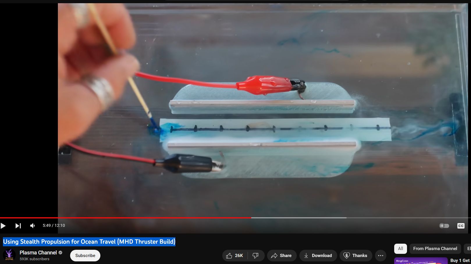
Using Stealth Propulsion for Ocean Travel
from video comments —
The “caterpillar drive” mentioned in “The Hunt for Red October,” a novel by Tom Clancy and its subsequent movie adaptation, refers to a fictional silent propulsion system used by the titular Soviet submarine, Red October. In the story, this technology, also known as the “magnetohydrodynamic drive,” allows the submarine to move through the water virtually undetectable by enemy sonar, giving it a significant strategic advantage.
### Magnetohydrodynamic (MHD) Drive: The Science Behind the Fiction
Magnetohydrodynamics is a real field of study that combines principles of both magnetism and fluid dynamics. It involves the motion of an electrically conductive fluid (such as saltwater) in the presence of a magnetic field. The basic principle behind an MHD drive system is to propel a vehicle through water by using a magnetic field to push the conductive water behind it, thus creating thrust.
In “The Hunt for Red October,” the caterpillar drive is depicted as a revolutionary silent propulsion technology. Unlike conventional propellers or turbine-driven propulsion systems that create noise and turbulence detectable by sonar, the caterpillar drive’s silent operation is what makes Red October a formidable threat and the centerpiece of the novel’s plot.
### Real-World Applications and Limitations
While magnetohydrodynamic propulsion is a concept explored in scientific research, its practical application, especially in the context described in Clancy’s novel, faces significant challenges:
– **Energy Efficiency**: MHD drives require a considerable amount of electrical power to generate the magnetic fields needed for propulsion. This poses a challenge for energy storage and generation, especially on a submarine.
– **Speed**: The speeds achievable by current MHD technology are relatively low compared to conventional marine propulsion systems, making it less practical for military applications where speed and maneuverability are crucial.
– **Technical Complexity**: Developing an MHD propulsion system that is compact, efficient, and powerful enough for use on a submarine involves overcoming significant engineering and materials science challenges.
Despite these limitations, the concept of silent underwater propulsion remains an area of interest for military and civilian applications. The idea of using magnetohydrodynamic drives to reduce the acoustic signature of submarines is particularly appealing for naval operations, even if the technology has not yet reached the capabilities fictionalized in “The Hunt for Red October.”
### Conclusion
The “caterpillar drive” from “The Hunt for Red October” serves as a fascinating example of how science fiction can inspire interest in real scientific principles and technologies. While the practical implementation of a silent, efficient MHD propulsion system for submarines remains largely in the realm of fiction, the underlying science continues to be a subject of research and exploration.
