Working ATT Skyway Microwave Relay Stations
The issue was not curvature, which is theoretical; instead, the issue was water absorption of microwave S and C band energies, which is appreciable, combined with appreciable beam divergence, combined with the maximum sensitivities attainable at receivers, combined with the safety limitations rightfully imposed upon terrestrial-layer signal power. The workable distance turned out to be several dozens of miles between stations, which re-amplified and re-focused the microwve beams.
I imagine some of those racks had multiplexers in them. It’s amazing you were able to power up the building after 25+ years. It is a testament to the quality of AT&T manufacturing that nothing shorted, blew-up, or caught fire. I was waiting for the magic smoke.
TOXI site and DR MAGDA HAVAS and DR DEVRA DAVIS and many many others want people to know that RF radiation splits DNA; split DNA causes cancer; therefore, RF rad causes cancer.
Rumor has it that immediately after power-up of the RF horns, a tremendous explosion was realized in distant Tunguska, RU…
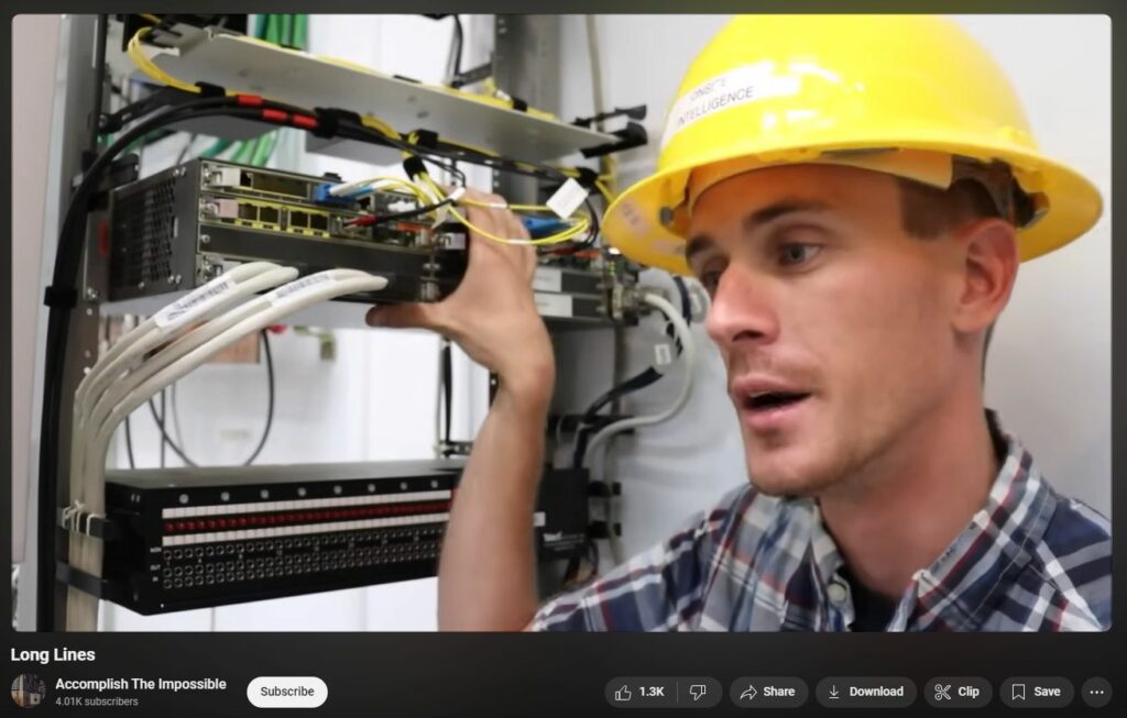
The “Microwave module” is actually a Nokia router with different module options (Verizon uses those Nokias). The top slots looks like fiber optic interfaces, and the bottom looks like a T-1 breakout module that’s probably connected (wired) to the Telect DSX panel right below it. Cell sites were originally fed via T-3 (DS3) microwave, which then had a demux (“M13” pronounced M-1-3) which took the T-3 and broke it out to 28 T-1 lines. That was fed to the DSX panel,, and patched up to the Nokia router module (the white cables). That style of “trunking” is long gone, and now cell sites are either fed by 10GB Ethernet or OC-192 SONET microwave (or higher nowadays via dedicated underground fiber to accommodate 5G speeds). The Nokia routers also have a special clock timing option to sync the transport network together, which is important in how Cellular networks work.
A great video on YouTube is a Bell System 1968 film called “Without Fail.”. Corn some reason it comes up as “The amazing unfailing Bell System. I watch it periodically to remind myself how great a system it was.
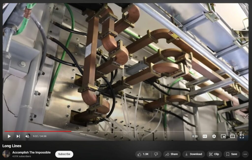
I was never associated with telephone communication so, don’t know any of the system design specifics. Making a long distance call in the 1970’s sounded like the system was using supressed carrier single sideband with multiple channel banks. A friend in 1982 told me the large antenna horns had a front-to-back ratio of 80 dB, which was necessary since the input frequency was the same as the output frequency. That waveguide looks to be sized for 5 to 6 GHz. Of course, high frequency solid state devices were not available so, klystrons were probably used as transmitters in the original 1950’s systems. Later, solid state RF power amps were used at lower frequencies, then multiplied up to the transmit frequency using varactor frequency multipliers.
They operated smack in the 4ghz satellite downlink C band. That is why up until the mid 1980s C band satellite receive stations also had to be licensed as the receiver LO could cause interference to the AT&T links. With the AT&T breakup and the proliferation of back yard C band receivers before scrambling, the FCC finally gave up on the C band receive license requirement.
es, klystons were used for the MW modulators in the first TD-2 facilities. Then TH radio was developed using TWT modulators, which have less noise. Then TD-2 was improved by solid stating it and using TWT’S instead of Klystons, it was labeled TD-3. Then it all went digital.
Thank you so much for helping to document the fascinating history of the long lines system. This is easily the most interesting video I’ve seen on it to date. It is so amazing to see a site that has most of the equipment in working order. I never thought I’d see somebody actually power up a site. It makes me wonder how many others are out there that are frozen in time, as if they were just simply switched off and left behind.
Southwestern Bell Telephone & Telegraph was one of the Regional Bell Operating Companies (RBOC) of the former Bell System. Long Lines was the part of the legacy AT&T that quite literally was responsible for all of the cables and later, microwave communications. AT&T Long Lines ceased to exist after the Bell System breakup and long story short, Southwestern Bell eventually was able to “swallow” its former parent, AT&T. It took on its parent name and became the current AT&T.
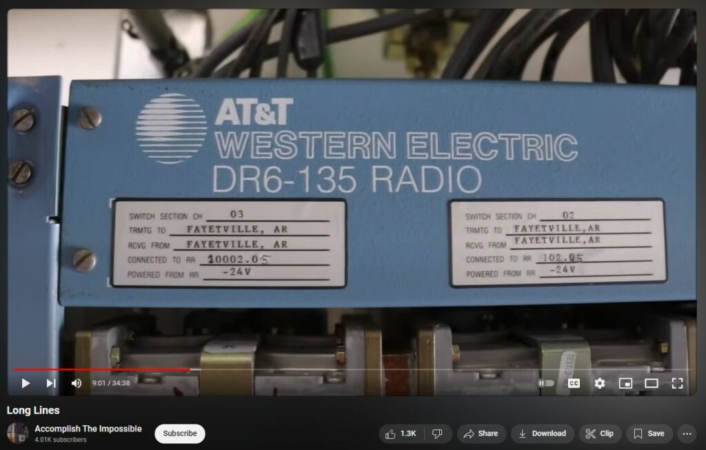
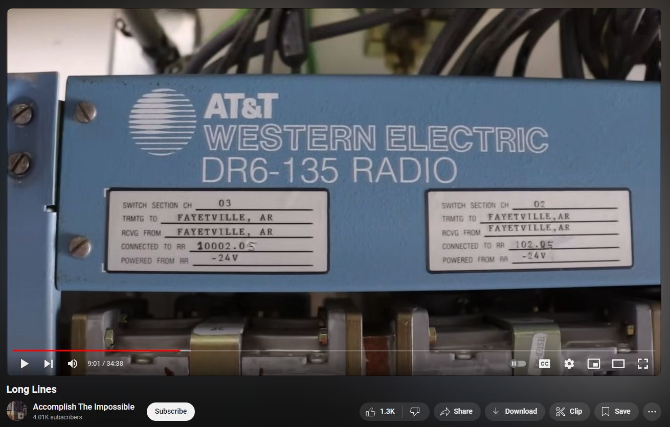
it looks to me like this is a very late technology version of the Long Lines system, probably updates not long before or even while the system was beginning to b4 phased out of use. The logo shown on the rectifiers, transmitter racks, and other systems is the post Bell breakup “Death Star” AT&T logo, which was first used in 1983. No less cool, but quite a bit more modern and MUCH smaller than the original fully vacuum tube hardware that would have been used when the first Long Lines stations went into service.
That equipment was all upgraded in the 80’s or 90’s. Those are all digital radios. The 1950’s Bell System Longlines network was all analog radios with analog A, L and other carriers. All of the equipment was gray and it had Bell System bell logos and said Western Electric in the old lightning font. The AT&T “Deathstar” logo didn’t come into existence until 1984. When they first started to switch from analog to digital, they used transmuxes that would take T1 spans and convert them to an analog L carrier (and back) so they could be transmitted over the existing analog radios. That site is clearly newer than 1984.


