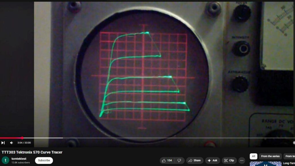
0:01
sometimes life is well unpredictable and
0:09
sometimes things just seem to be the way they work supposed to be what you see on
0:18
the screen is a trace of a pentode
0:24
vacuum tube it is being displayed on a
0:30
Tektronix model 570 characteristic curve
0:36
tracer so what do those two have how do I know what time that was two together
0:43
well I wanted to return to I wanted to
0:53
wait one more video and I wanted to
0:58
return to electronics if I could as many of you know I've been off doing some
1:05
kind of wrapping up a review of my astronomy hobby and things like that but
1:13
my second love chronologically that is
1:19
was electronics I started out with astronomy and chemistry but because I
1:26
got a telescope and a chemistry set when I was 9 but by the time I was in middle
1:33
school they called it junior high back then electronics was the thing that I
1:38
loved the most and of course being in the 1950s that meant vacuum cubes well
1:47
Oh a couple of weeks ago my UPS delivery
1:53
man stopped me I was out in the front
2:00
yard as he was delivering something and said you're interested in vintage
2:06
electronics tubes and things like that aren't you and I said yes I wondered why
2:12
he how he knew that turns out he has delivered so much thanks to me that he
2:19
knew it and he also had a background in electronics he had worked for Raytheon
2:25
back in I think in the in the eighties
2:31
doing some electronics work and so he said you wouldn't be interested in an
2:37
old Tektronix curve tracer would you I mean my eyes lit up it was like you know
2:46
it would be like asking the Albert Einstein I'm no Einstein but like asking
2:52
Albert Einstein would you be interested in relativity yeah so he sold me this
3:00
curve tracer and I've been playing with it for the last week or so and so it is
3:06
I think fitting has a return a video
3:13
return to electronics and so you know if
3:19
I had to if I had to close out in on anything this would be it at any rate
3:25
enough about me in the history in my UPS man what this device does is it displays
3:35
various current and voltage characteristics graphically along the
3:42
the vertical axis it displays the current through the tube and along the
3:49
horizontal axis it displays the voltage in this case it's the play current verses play voltage and the
3:58
stamps are varying grid vote values so let me show you the block diagram of
4:06
this device and then come back and show you how it works a little bit and and
4:11
then we'll do we'll run a couple of tubes on it and see how it how it works
4:18
now it has a neat feature that it allows you to switch quickly between one tube
4:25
and another tube I'll save for later who of what those tubes are but these are
4:31
two pen toads that are being displayed and you see there's a difference in that
4:37
one and in that one though there's not a lot of difference notice that the top is
4:46
very close to the the top trace of this one so let's take a look at a block
4:53
diagram so here is the block diagram of the Tektronix 570 by the way this device
5:01
was built in 1955 I was 10 years old on
5:08
the left is a is the shaper for the
5:14
stepping voltage you remember you you saw that it would step the grid voltage it starts with this stepping voltage
5:23
shaper that feeds a step generator then
5:28
that is amplified by the step amplifier and can be applied to the grid of the
5:34
tube this is the device under test and there's space for two of these so that
5:39
you can switch between them well look at that a little bit later the so for the
5:48
display we just saw the step is applied to the grid the cathode is grounded the
5:57
plate is connected to the horizontal amplifier and also to the plate sweep
6:04
generator now the what the plate suite generator does it generates a a sweet voltage that can
6:12
go up to I think 500 volts on the 570 so
6:18
so it can be anything as little as 1 volt let's see it's the no 5 volts it's
6:27
the traditional Tektronix to 510 so it's 5 10 20 50 a hundred two hundred five
6:36
two hundred three hundred five hundred volts so it applies that to the plate
6:43
and then you can read out the plate through the horizontal amplifier while
6:49
the the current through the tube is
6:56
measured by the let's see vertical amplifier and the way it does that is
7:04
the current through the plate sweep generator is flows through this resistor
7:10
and so it taps the voltage off of that so this allows you to measure plate
7:15
current on the vertical while measuring plate voltage on the horizontal and
7:21
that's the display we just saw a minute ago so this is the basic diagram of the
7:28
five seventy so this is a printout from
7:34
the five seventy manual showing the
7:40
plate current versus plate voltage and
7:46
in this case this is for a six u 8 now a six u 8 is a two section tube it looks
7:58
like this
8:06
notice that one section is a triode and one section is a pentode let me let me
8:18
just pick that up and take it a little closer to the camera so that you can see
8:23
a little better what that looks like so you see that it's a yeah it's a triode
8:31
on the right and a pentode on the left these tubes were used in early
8:40
television sets to generate the vertical
8:45
sweep the triode section was used for the oscillator and the pentode section
8:52
was used to drive the yoke I'm not going to get into television Theory here but
8:57
basically that is the way that the the signal would be swept across the screen
9:02
from top to bottom there was also a horizontal sweep system that would sweep
9:08
it from left to right so what you see here are a series of stamps and on the
9:16
left are the setups for this so in the
9:21
manual one of the things that they part of the training of someone on using the
9:26
570 was to set up a 6u 8 and by the way it even I think originally came with a
9:33
68 tube fortunately I have some new old stock tubes and was able to dig up a
9:41
couple of 6u eighths but the basic idea
9:48
of this is it allows particularly a design engineer to measure the
9:57
characteristics on a particular type of tube it also allows someone to compare
10:03
the characteristics of two tubes for example suppose that you have a dual
10:11
triode like a 6s n7 where there are two triodes in the same package well you can
10:18
switch between those two using the switch that I used earlier and
10:23
compare to see how well matched they are so there were basically two applications
10:30
for this device one was for design engineers who were designing tube circuits to be able to find out the
10:40
characteristics of the tubes they were using so that they could design the
10:45
circuit around those characteristics and the second which has come into even much
10:51
more use these days is the matching of
10:56
tubes the because of the resurgence of
11:02
vacuum tube amplifiers both for guitars and for high fidelity the need to match
11:09
tubes particularly since you're dealing in many cases with new old stock tubes
11:15
that have been around for 50 60 70 years is finding a pair of tubes for example
11:22
that have similar characteristics so that they they don't require a lot of
11:30
imbalance in the amplifier to work correctly so for example in a push-pull
11:36
stage output stage and if you want to know more about that there are some
11:41
videos I did on how tubes work and and vacuum tube circuits that you might want
11:48
to look at at some point but at any rate these days these are used by places that
11:59
specialize particularly in tube electronics generally amplifiers to
12:05
match tubes and do other things for me I was just it's just a toy and I'm glad I
12:13
was able to acquire one of these it's almost like it was it was ordained here
12:22
you see the characteristics of a triode what we looked at just a minute ago was
12:29
the pentode section this a triode of a six gh8 - if you look on
12:40
the left at the pinout you see it is and I don't expect you to remember the six
12:46
u8 but take my word for it it is exactly the same pinout as the six you ate the
12:51
six gh8 was the replacement for the six you ate it had a little more
12:59
transconductance and could handle higher voltages so the six GH 8 and the six you
13:08
ate that we saw a minute ago are both medium mu triose mew just means the
13:16
amplification factor and a sharp cutoff pentode so these are what you would
13:27
display for the triode section of that same cube so let me show you a little
13:34
bit about how the 570 is set up and then we'll talk a little bit about how you
13:41
might use something like this though I will admit this is really just a boat
13:47
anchor okay there there is an application for it in in tube matching
13:54
for amplifiers but frankly there are solid-state versions of these kinds of
14:01
things that can be done and they work better because they work on a computer
14:06
so you can log the data and analyze it better and so on but for for a dinosaur like me to come
14:14
across one of these things is sort of the find of a lifetime they are very
14:20
expensive on YouTube I saw one a bay I saw one that I looked for and by the way
14:28
the the UPS delivery man and I had quite a long discussion several times I said
14:35
do you realize how much these might be worth and he said yeah but I just don't want to pack the thing up so if I could
14:43
just deliver it that's what I would like to do and sure enough he showed up with it and and my
14:50
one of my dreams of a lifetime came true so I said I'd get away from me let's get
14:57
back to the five seventy and a little bit about how you set this up here is
15:03
the rat's nest patch patch cords
15:08
whatever you want to call it that you set up a tube with along the top you see
15:14
are a series of binding posts on the left are two for heater same on the
15:21
right let me move this turn this to get a little better light on that there we
15:28
are then there are crowns for the cathodes and notice these are symmetric
15:34
then there is grid a and grid B there is
15:40
a minus voltage that you can apply to the Tobias that you there is a plus
15:46
voltage and this is the one place where they are so it begins to be asymmetric
15:51
there is a plate connection and there is a minus DC connection so what are all of
16:01
these for well the grids are the step voltage that we talked about earlier the
16:08
the plate is where you read the plate voltage and the plate current the DC
16:14
plus is to allow you to bias the screen grid for example of a pinto tube and the
16:22
DC minus is in case you need to bias a APN on a tube to a particular level as
16:31
well as the - 150 27 K which has a kind
16:38
of special function that I'm not sure if I'll get into all of that
16:43
but on the face of the 570
16:57
on the right you get a little more light
17:05
on this well something like that you see
17:16
on the right here is a voltmeter that you can select and down below is what it
17:25
shows and it allows you to adjust the heater voltage the positive and negative DC voltage as well as the range of the
17:32
meter then below that let me readjust
17:38
this tripod beneath the meter is the
17:45
step generator and you notice that it allows you to either do 120 or 240 steps
17:53
per second and you can adjust with the red knob the number of steps per family
18:00
I'll show you that in a second on the right is the volts per step and the
18:07
start adjust in other words where that step voltage starts normally you want it to start at zero and you notice that
18:14
there is a little zero marking right here where where this is set right now
18:20
beneath that is the CRT display it
18:28
adjusts the vertical and horizontal sensitivity as well as the vertical and
18:34
horizontal position down here moving to
18:41
the left pardon the moving the tripod here you
18:48
see at the very bottom is the adjustment for the minus DC voltage above that or
18:54
the operating voltages you can set the heater voltage for anywhere from about
18:59
1.2 volts up - I think it's 117 volts so
19:04
pretty wide range of heaters and it adjustable so for example you can run a tube at below or above its normal heater
19:12
voltage to see what that does to the characteristics the this is the control
19:21
for setting the positive DC voltage like for example the screen grid it has both
19:27
a step and an adjustable and by the way this is sort of the traditional Tektronix layout they used for decades
19:35
there while this is a specialized oscilloscope the the main the bread and
19:42
butter of Tektronix were their general-purpose oscilloscopes and they
19:48
used this same basic control setup so once you learn how to use one Tek you
19:53
could use another above that is the
19:58
plate sweep generator that you notice allows you to set the peak volts up to
20:04
500 volts and to adjust the size of the series load resistor finally over here
20:12
is the mains odd to now turn on and you
20:18
notice a little bit of a sound from the fan then you can turn on the test
20:25
voltage and and the reason for this switch is so that there is no voltage on
20:32
this test panel until you're ready for it so in other words you don't have to
20:39
move these wires around while there's voltage on the on the test panel so now
20:45
we're going to turn the test on and you may notice up here
20:52
on the meter it now shows a hundred volts is the plus DC voltage I have it
20:57
set to the plus DC position so now let's
21:05
move this tripod up a little bit turn off some of this light
21:18
and turn up the intensity and turn on
21:25
the grid grid a then and what I'm doing
21:32
is I'm flipping this switch down here from the grid a position to the grid B
21:37
position I know you can't see that because of the glare from these pilot lights but here is grid a that's one
21:45
cube here is grid B and you notice there's a setting in between for 0 what
21:52
that is doing is switching between the grid of this tube and the grid of this
22:00
tube or in the case if you wish you can have two grids of the same tube like a
22:06
dual do dual triode where there are two triodes in the same section and it all
22:12
depends on how you have these wires set up so that is basically how the 570
22:20
works and how you operate it I'm I'm not
22:28
going to go through an extensive you know showing a bunch of different tubes and all of that I'm not sure what
22:33
purpose that would serve though I do realize a few people might be interested in seeing their favorite tube on a 105
22:40
70 but instead what I'm going to do is talk a little bit about some small
22:47
changes that I made to this to this 570
22:53
that improved its performance a little bit
23:00
and one thing the of course they needed
23:05
a cleaning and I cleaned out the interior pretty well vacuumed out as
23:12
much of the dust as I could get cleaned the tubes off and did a pretty good cleaning on the switches and other
23:18
things basically the same thing you do anytime you're restoring a vintage piece of equipment other than that it the the
23:27
unit worked right off the bat so but it had a few quirks and fortunately I was
23:36
able to find and remember a few of the little changes and so things that people
23:43
have done over the years and one of them I'll show you on the schematic take
23:52
Tektronix normally did a wonderful job in fact their equipment was over
23:58
engineered but on this 570 they did make one little design error and and so let
24:08
me show you how I fixed that and since then this unit has performed beautifully
24:14
this is the schematic of the step amplifier in other words the the
24:22
amplifier that takes the the step voltage and buffers it amplifies it and
24:32
provides it to the grid a grid B switch that you see here so let me zero in on
24:38
this part of the schematic so this is
24:45
the final power stage of the step amplifier it consists of a 6c l6 pentode
24:55
and you may notice that the plate is driven directly off the minus 400 volt
25:02
unregulated supply and the cathode is driven through this 120 K resistance 300
25:13
volt unweighted so plus 400 on the plate - 300 on the grid on the cathode
25:20
resistor and then this is a cathode follower the so the signal comes out of
25:27
there and is switched by this grid a grid B switch to the grids of the tubes
25:34
well one of the problems that this stage has is the unregulated supply is located
25:44
a long way away from this 60 l6 and because it does draw a very fairly
25:51
high currents it can it can oscillate
25:57
now early on I think the tech engineers thought that the oscillation was due to
26:04
parasitics in the pen in the test panel of the patch panel and so they released
26:10
some resistor jumper wires to try to
26:15
suppress that and that still does sometimes happen with certain particularly high gain high frequency
26:25
tubes tubes fused for example at UHF frequencies back in the day but the real
26:32
problem with this wasn't it was the decoupling of the minus and plus
26:37
unregulated supplies so all that I needed to do was to add a capacitor very
26:46
close to this tube from the minus regulated and I used to point to 2 micro
26:52
farad you could use a bigger or smaller one just be sure that the voltage rating is sufficient between the minus supply
27:01
and ground and the plus supply and ground and that cleans up the the what
27:09
appears to be oscillation on the grid signal which of course also appears on
27:15
the plate once you have changed the circuit to do that this particular unit worked perfectly
27:22
now there were a few other little issues with the 571 I've already mentioned the
27:30
fact that some tubes would oscillate and and that you could help that by
27:37
suppressing the grid let's go back to this picture here the connection between
27:46
this point and the grid could be replaced by a small resistor patch cord
27:54
that would it's basically called grid suppression and the resistor is often
27:59
called with suppression resistor it was a common way of getting rid of parasitic
28:05
oscillation in tube circuits it's still used in transistor circuits today there
28:10
there are times particularly with MOSFETs where you have to insert a small resistor in the gate lead to keep the
28:19
stage from oscillating but except for
28:24
those a couple of small things and a little bit of maintenance and a little bit of recalibration I was able to get
28:32
this 572 work and it was pretty much working when I got it it just needed a
28:38
little perking up don't we always at our age so oh I think what I'm going to do
28:46
oh I did want to mention something that before I before I finish and that is
28:56
that the plugins that it comes with it
29:04
comes with the pair of octal plugins I'm using the nine pin up plugins right now
29:11
for the the tubes that are in there it comes with a pair of seven pins logins
29:16
it of course comes with a series of patch cords and things of that sort but
29:21
one thing it doesn't come with is a way to do the characteristics of octal tubes
29:28
now back in the day the most prominent tubes were octal
29:35
seven pen and nine pen but Philco partly
29:47
just to get around patent restrictions came up up with a tube type that they
29:53
called a lock ttle let me show you one of those here it looks like this notice
30:05
that there's a small indentation there
30:11
in the in the locating pin other than that it basically is an octal tube these
30:17
pins are smaller physically but they're the same eight pm configuration that oh
30:24
but there's no way to test these or to display these characteristics on the 570
30:29
but there is an easy solution to that and that is if you take a I'm gonna get
30:36
one of these over here if you take an octal tube base that you can buy these
30:42
are very readily available today and you
30:47
pair it with a lottle socket now all that is all that's inside this is just a
30:54
wire from that pin to that pin all the way through in other words eight wires
30:59
just going straight through from side to side and then pull through on the other
31:04
side and soldered but what that allows you to do is to test our lock dual tubes
31:10
which sort of completes the collection
31:16
from the day now if you want to test newer tubes you can do so the problem is
31:24
that the most pins that any of these sockets have is 9 p.m. so if you try to
31:31
display a compact Ron for example you're going to run out of pins if you try to
31:37
connect all of the pins of a John because that has 12 or an O var
31:42
that has 12 pins and there's only a total of nine pins available on the 570
31:51
but you can still do it using the same
31:58
technique you just need to be clever about the or Frugal maybe in the way you
32:03
use your connections so that is my
32:15
experience with the Tektronix type 570
32:22
characteristic curve tracer I hope you've enjoyed this and I hope you've
32:30
enjoyed my other videos at any rate I do
32:36
hope that things will go well for you in the future and look forward to getting
32:42
through this Corona thing civilization will endure and and so I know that
32:49
there's they're happy futures ahead at any rate for now I want to say thanks
32:57
for watching