Ground Resistance Testing with Electrical Code expert Mike Holt
“Stray current” is a real danger.
Ground resistance testing is a crucial aspect of electrical safety and compliance with electrical codes. The process involves measuring the resistance of the grounding system to ensure that it meets the required standards for electrical safety.
In a real-world experiment with electrical code expert Mike Holt, ground resistance testing may involve the following steps:
1. Selection of Testing Equipment: Holt may begin by selecting the appropriate ground resistance testing equipment for the specific application. This typically includes a ground resistance tester or a clamp-on ground resistance tester, as well as test leads and auxiliary equipment such as grounding stakes or rods.
2. Preparation of the Test Site: Holt would then prepare the test site by ensuring that the area around the grounding system is clear and accessible. Any surface debris or vegetation that could interfere with the test should be removed, and the grounding electrodes should be exposed for testing.
3. Connection of Test Equipment: Holt would connect the ground resistance tester to the grounding electrodes using test leads or clamps. The tester would be configured according to the manufacturer’s instructions, including the selection of the appropriate test method (e.g., three-point or four-point testing).
4. Execution of the Test: With the test equipment properly connected, Holt would execute the ground resistance test by applying a test current to the grounding system and measuring the voltage drop across the electrodes. The tester would calculate the resistance of the grounding system based on Ohm’s Law (R = V/I), where R is the resistance, V is the voltage drop, and I is the test current.
5. Interpretation of Results: Based on the measurements obtained during the test, Holt would interpret the results to determine whether the ground resistance meets the requirements specified by the applicable electrical codes and standards. This may involve comparing the measured resistance to the maximum allowable resistance specified in the code or conducting additional tests to verify the integrity of the grounding system.
6. Documentation and Reporting: Finally, Holt would document the results of the ground resistance test and prepare a report detailing the findings. This report would typically include information about the test methodology, equipment used, measured resistance values, and any recommendations for corrective action if the grounding system fails to meet the required standards.
Overall, ground resistance testing with an electrical code expert like Mike Holt is an essential process for ensuring the safety and reliability of electrical systems, and it helps to verify compliance with electrical codes and standards.
Understanding Ground Resistance Testing: Insights from Mike Holt
Ground resistance testing plays a crucial role in ensuring electrical systems are safe, reliable, and efficient. Electrical code expert Mike Holt’s real-world experiments highlight the importance of this process in protecting people and equipment from electrical faults.
What is Ground Resistance Testing?
Ground resistance testing measures the ability of the earth to dissipate electrical currents. This process is vital in creating effective grounding systems that protect against surges, faults, and lightning strikes. Poor grounding can lead to equipment damage, electrical hazards, and system failures.
Mike Holt’s Real-World Approach
Mike Holt, a renowned electrical code expert, emphasizes practical, hands-on methods for understanding ground resistance. His experiments showcase how varying soil conditions, grounding rods, and installation techniques affect resistance values.
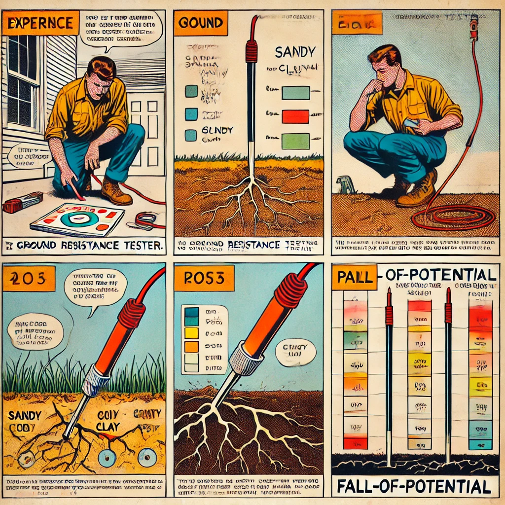
In one demonstration, Holt tested grounding in different environments, such as sandy soil, clay, and rocky terrain. These experiments revealed significant variations in resistance levels, underscoring the importance of site-specific evaluations. Holt’s findings align with industry standards, which recommend resistance values below 25 ohms for effective grounding.
Techniques and Tools
Holt’s approach highlights the use of advanced tools and techniques for accurate measurements. Devices like earth ground testers measure the resistance between grounding systems and the earth. Holt also demonstrates the importance of proper grounding rod installation, ensuring deep penetration and secure connections to minimize resistance.
One innovative method he discusses is the fall-of-potential testing technique, which measures resistance by analyzing voltage drops across electrodes. This method provides precise insights into the effectiveness of grounding systems, even in challenging environments.
Real-World Challenges
Holt’s experiments address common challenges in ground resistance testing, such as:
- Environmental Factors: Soil composition, moisture levels, and temperature significantly impact resistance values. Understanding these variables helps in designing efficient grounding systems.
- Rod Placement: Improper spacing or shallow installation of grounding rods can lead to high resistance values. Holt emphasizes the importance of correct placement and alignment.
- Equipment Calibration: Using calibrated and well-maintained testing equipment ensures accurate readings and reliable results.
Practical Applications
Ground resistance testing is essential in various applications, including:
- Industrial Facilities: Ensuring safe operation of machinery and equipment.
- Residential Systems: Protecting homes from electrical faults and lightning strikes.
- Renewable Energy: Safeguarding solar and wind installations against electrical surges.
The Takeaway
Mike Holt’s experiments provide invaluable insights into the practical aspects of ground resistance testing. By addressing real-world challenges and emphasizing hands-on techniques, he equips electricians and engineers with the knowledge to ensure safer, more efficient electrical systems.
For professionals and enthusiasts alike, understanding the principles of ground resistance and its testing methods is a cornerstone of electrical safety. Holt’s work underscores the importance of continuous learning and adapting to evolving industry standards.