An examination of how power supply design affects audio circuitry and ultimately sound quality
Great. I’ll conduct an in-depth investigation into how power supply design affects audio circuitry and ultimately sound quality, considering both objective performance and subjective perception. This will include foundational and recent research, and apply to all categories of audio equipment, from consumer to professional.
I’ll explore how regulation, capacitive storage, supply type (linear vs SMPS), and electrical layout contribute to noise, distortion, slew rate, and other audio parameters—including psychoacoustic and system-level effects.
I’ll get back to you with a structured report and bibliography.
Introduction
Power supply design is a crucial foundation for audio electronics. Every amplifier, processor, or analog stage ultimately modulates its power source to create sound – in essence, “an audio amp is simply a modulated power supply” as one engineer aptly noted. The quality of that power – in terms of stability, noise, and impedance – can profoundly influence both measurable audio performance and the subjective listening experience. This report explores how power supply design choices affect audio circuitry and sound quality, covering objective metrics like distortion and noise as well as psychoacoustic perceptions. We consider all types of audio components (consumer/professional, analog/digital) and review both foundational theory and recent findings to provide a comprehensive analysis. Key topics include power regulation (strict vs. loose vs. unregulated) and its impact on distortion and slew rate, low-frequency stability (motorboating), psychoacoustic effects of power supply stiffness, emissions from switch-mode supplies, mains-frequency transformer hum, ground loops, electromagnetic coupling in layouts and components, the role of capacitive energy storage, and even the contentious realm of boutique cables and ultrasonic signal integrity. Supporting references are provided throughout to ground the discussion in established research and measured evidence.
Power Supply Regulation and Audio Performance
One of the core design choices is whether to use a regulated power supply or leave the supply unregulated (aside from basic rectification and filtering). A strictly regulated supply holds the voltage rails constant under varying load, whereas an unregulated supply’s voltage will sag under load and rise when lightly loaded. This choice directly affects objective performance metrics:
- Distortion (TIM, THD) and Slew Rate: Amplifiers with inadequate power delivery can exhibit higher distortion. If the supply rails dip during transients, the amplifier may effectively starve for voltage or current, introducing slew-rate limiting or transient intermodulation distortion (TIM). In extreme cases, a sudden demand may cause the amplifier’s input stage or voltage gain stage to saturate or slew slowly, producing TIM as described by Ottala’s theory. A stiff supply that doesn’t droop helps prevent such conditions. However, a poorly designed regulator can itself become a bottleneck – for example, if the regulator cannot respond quickly to rapid current changes, the “response to transient current demands is likely to be relatively slow, affecting slewing behavior”. Thus, a well-designed regulated supply can reduce distortion (by maintaining stable voltage), but an inadequate regulator may inadvertently introduce high-frequency distortion or even oscillation. In fact, complex regulator output impedance can cause bizarre high-frequency instability in some amp/regulator combinations. Overall, low supply impedance is key: if supply voltage remains steady even during bursts, the amplifier can cleanly reproduce fast transients without added nonlinearities.
- Total Harmonic Distortion (THD) and PSRR: A clean, regulated supply will have minimal ripple, which means the amplifier’s power supply rejection ratio (PSRR) isn’t heavily taxed. Any hum or ripple that does exist on the rails can modulate the output and appear as added THD or intermodulation products. A classic unregulated supply has significant 100/120 Hz ripple after rectification, so a power amp must rely on its PSRR to keep hum out of the output. Good designs achieve hum below –100 dBu even with unregulated rails. A regulator can essentially eliminate ripple, allowing even amplifiers with mediocre PSRR to achieve low output hum. That said, designers caution that “you can only afford to be careless with the PSRR of the power amp if the regulators can maintain completely clean supply rails in the face of sudden current demands”. If a regulator cannot source a large transient quickly, the rail may momentarily droop or inject noise, and this could worsen distortion or even cause interchannel crosstalk in stereo amps (one channel’s heavy draw modulating the other’s supply). Multiple regulators or an oversized regulator are solutions. In short, regulation can lower THD by removing supply hum and preventing rail sag, but only if the regulator design keeps up with dynamic currents.
- Noise (Audible, Sub-Audible, Ultrasonic): Power supplies contribute to the noise floor in audio systems across the spectrum. Audible noise from the supply typically appears as hum (50/60 Hz mains leakage or 100/120 Hz ripple and their harmonics) or as broad-band hiss if the supply/regulator itself generates noise. For instance, certain IC regulators have noise specifications – a poorly chosen regulator can introduce more microvolt-level hiss than the audio circuitry! A well-filtered linear regulator often has noise below the amplifier’s own noise floor, but high-frequency switching regulators might inject ultrasonic noise if not filtered. Sub-audible noise includes very low-frequency fluctuations: e.g. “motorboating,” a low-frequency oscillation (discussed next), or slow supply drift – these can manifest as slow output wafting or instability. Ultrasonic noise from supplies (e.g. switching spikes from an SMPS at tens of kHz) is inaudible directly, but can cause intermodulation within the audio band or trigger non-linear behavior in circuits. If an amplifier has non-negligible gain at high frequencies or if diode switching transients from rectifiers are not snubbed, ultrasonic junk can sneak in. In fact, even a simple diode bridge in a linear supply generates RF bursts at each rectification cycle as the diodes switch off, at ~100 Hz repetition – as load current increases, these RF bursts worsen. While typically filtered by reservoir capacitors and bypass capacitors, such HF noise can potentially couple into sensitive analog stages or radio receivers. The bottom line is that a strictly regulated supply tends to minimize low-frequency noise (hum) but could add some high-frequency noise (regulator self-noise or oscillations), whereas an unregulated supply may have more hum that must be filtered/PSRR’ed out, but no high-frequency switching noise. Modern designs often use a hybrid approach: a switching pre-regulator followed by linear post-regulators to get the best of both – efficient power delivery with minimal high-frequency noise.
Regulated vs Unregulated – A Summary of Trade-offs: In audio power amplifiers, designers have long debated the merits of unregulated “stiff” transformer supplies versus adding regulators. A recent engineering analysis boils down the trade-offs as follows:
- Unregulated Supply (Transformer + Rectifier + Caps): Advantages: Simple, cost-effective, and inherently able to deliver higher peak currents than its continuous rating – the supply voltage will sag under heavy load, but this allows the amp to momentarily draw extra current for transients (yielding dynamic headroom for short bursts). No high-frequency switching means no risk of SMPS interference. Simpler design is often more reliable. Disadvantages: Output power varies with mains and load – e.g. power into 4 Ω is less than double that into 8 Ω because the rails droop under load. Significant ripple is present, demanding good PSRR or heavy filtering to avoid hum. The supply impedance is not zero, so the amplifier’s output is not a perfect voltage source. Also, large transformers can radiate magnetic fields and induce hum in nearby circuits (discussed later). Despite ripple, properly designed unregulated supplies can achieve hum below audible thresholds with careful filtering.
- Linear Regulated Supply: Advantages: Holds rail voltage constant regardless of load or mains variation, so the amp’s clipping point is fixed – no “sag.” This yields more consistent power output; theoretically a regulated amp acts closer to an ideal voltage source that doubles power from 8 Ω to 4 Ω load. Clipping, when it does occur, is “cleaner” since the saturation of output transistors isn’t exacerbated by rail ripple or droop – the clipped waveform isn’t modulated by supply sag. With good design, ripple can be virtually eliminated, relaxing the PSRR requirements on the amp and reducing hum to negligible levels. Disadvantages: Complexity is much higher – essentially adding another feedback loop (the regulator) in series with the amplifier’s own loop. This doubles the opportunity for instability (“a deadly embrace if one partner oscillates” as one author quipped) and can introduce high-frequency instability if the regulator’s output impedance rises at certain frequencies. The regulator must be able to supply large transient currents; if not, it may limit peak power – unlike unregulated, a regulated supply prevents the amp from exceeding its nominal rail voltage even momentarily. So you trade away some short-term headroom. There is also higher heat dissipation (voltage dropped in regulator = wasted as heat) and cost/complexity of additional pass transistors, heatsinks, protection circuits, etc.. A failed output transistor can take out the regulator too in a “domino effect” if not carefully protected. In practice, very few high-power amps use fully regulated high-voltage rails – it’s often deemed not worth the complexity for large output stages. However, low-level stages (preamps, small-signal op-amps) commonly use regulated ±15 V or similar, because the current demands are low and the noise/ripple benefits are significant.
- Switch-Mode Power Supply (SMPS): Advantages: Light weight and compact, with no bulky mains-frequency transformer. Can be designed for universal AC input (90–264 V) easily. Good efficiency and less heat. When well-designed, can have fairly low ripple (though usually a bit higher residual ripple than a linear regulator, e.g. ~20 mV p-p is typical). Can include built-in protection (shut down on fault) and can often be purchased as a module. Disadvantages: The noisy emissions are the biggest concern – SMPS are “prolific sources of high-frequency interference”. Without careful filtering, switching spikes and harmonics can leak into the audio path as buzzing or hissing or cause radio interference. Even with filtering, RF noise from an SMPS can couple into sensitive analog stages or radiate into cables. Also, many SMPS still produce some low-frequency (100 Hz/120 Hz) ripple after the rectifier front-end, so an amplifier using an SMPS might still need decent PSRR. Another drawback is that SMPS typically have a current limit – they may shut down or drop out if an audio transient demands more current than the supply is rated for, whereas an unregulated linear supply might just sag a bit and recover. Additionally, designing an SMPS that is stable over all loads and has no odd interactions is an art; hence many audio companies buy proven modules rather than design from scratch.
In practice, each approach can yield excellent measured performance if well executed. As engineer Douglas Self concluded, “if properly designed, all three approaches can give excellent sound” – the key is that each requires different techniques to mitigate its weaknesses. Unregulated supplies need sufficient filtering and amplifier PSRR to keep hum and noise low. Regulated supplies need robust stability and fast response to avoid limiting dynamics or oscillating. SMPS need superb filtering and layout to prevent HF noise intrusion. Many modern high-end designs therefore mix strategies: for example, using an unregulated or switching main supply for power amp sections (for maximum current) while using local linear regulators for preamp or DAC sections to ensure low noise.
Motorboating and Low-Frequency Stability
“Motorboating” is a classic low-frequency oscillation in audio equipment, named for its puttering sound like an idling boat engine (repeated “putt-putt” in the speaker). It typically occurs at a few Hertz (below audible range, but heard as pulses) and is a symptom of a power supply feedback loop issue. In vintage tube amps and some analog circuits, motorboating happens when the power supply can’t adequately decouple different stages. Essentially, a heavy low-frequency demand from a power amp stage causes a dip in the supply voltage, which then feeds into earlier stages and creates a feedback loop. The cycle repeats at a low frequency, causing oscillation.
Motorboating is strongly tied to power supply impedance at low frequencies. An unregulated supply with inadequate reservoir capacitance or isolation between stages can allow the output stage’s current draw to modulate the supply line for the input stage. In tube amps, this was common: the plate supply for all stages might be distributed through RC decoupling networks. If those capacitors are too small (high impedance at bass frequencies), the stages are effectively coupled and can oscillate. As the Wikipedia entry notes, the high output impedance of rectifier tubes plus dried-out filter capacitors often led to low-frequency “sub-audio oscillators” in old designs.
A regulated supply, on the other hand, if properly designed, presents a low impedance across frequencies and can prevent motorboating. By holding the voltage constant and stiff, it avoids the scenario where one stage’s draw starves another. Indeed, one textbook solution to cure motorboating in vintage gear is to “add modern IC voltage regulators, or replace the entire power supply with a modern regulated one”. Regulation or simply bigger decoupling capacitors will break the feedback loop by keeping the supply steady. However, note that if a regulator itself isn’t stable at very low frequencies (or if its output capacitor is insufficient), a poorly designed regulated supply could oscillate at low frequency as well – though that is rarer.
In summary, motorboating is a symptom of inadequate low-frequency decoupling. The cure is to lower the supply impedance at those frequencies: either by increasing capacitance (doing “a capacitor job” to replace or add filter caps) or by adding regulation to stiffen the supply. Modern solid-state amplifiers rarely motorboat because they tend to have ample power supply filtering. The phenomenon is mostly of historical interest, but it underlines the importance of power supply design: designers must ensure each gain stage is properly decoupled (often using RC or LC filters between the main supply and sensitive stages) so that low-frequency feedback via the supply does not occur. If you ever see woofer cones pumping slowly in and out with no input signal (a visual indicator of subsonic oscillation), suspect the power supply decoupling first.
Psychoacoustic Impacts of Regulation (Subjective Perceptions)
Beyond objective metrics, audio enthusiasts often debate the subjective sound of different power supply designs. Can human ears perceive whether an amplifier has a tightly regulated supply or a loosely filtered one? This enters the realm of psychoacoustics and sometimes audio folklore, but a few points stand out:
- “Tighter Bass” and Dynamic Punch: A common audiophile claim is that amplifiers with more robust power supplies (e.g. large capacitive banks or regulation) have tighter, firmer bass. The idea is that a stiff supply better controls the amplifier output, especially in bass transients, leading to more defined low frequencies. In contrast, an amp with a wimpy supply might have “softer” bass as the rails sag on big hits (slightly compressing or blurring the transient). However, objective analysis tends to be skeptical of these claims. In one engineering article, the author noted that advocates of regulated supplies tout “tighter bass” but “are always careful not to define it too closely, so no one can disprove the notion. If the phrase means anything, it presumably refers to changes in low-frequency transient response; however, since no such changes can be objectively detected, this appears to be simply untrue.” In other words, a well-designed unregulated amp can have bass just as tight, given sufficient capacitance and damping factor. The subjective reports may stem from slight differences in frequency response or distortion that are below standard measurement thresholds – or from expectation bias. That said, in cases where a power supply is under-sized, the audible effect of supply sag can be a form of transient compression, which a trained listener might describe as less “punchy” bass. Thus, a grossly inadequate supply can definitely dull the sound, but between two well-designed supplies (regulated vs not), controlled tests have found minimal audible difference.
- Headroom and “Ease” of Sound: Another subjective aspect is how an amplifier handles musical peaks. An unregulated supply might allow a short burst above its continuous rating (extra headroom), which could make the amp sound more effortless on transients. A regulated amp will clip more abruptly at its limit, which could be perceived as a difference in “ease” or “strain” on loud passages. However, if both are designed not to clip within the usage range, this may not come into play. Some guitar amplifiers deliberately use sagging unregulated supplies to create a warm compression on peaks – that is a deliberate distortion for musical effect. In hi-fi, the goal is usually transparency, so we generally don’t want audible compression from the supply.
- Imaging and Noise Floor: Psychoacoustically, the noise floor of a system (even if inaudible as hiss) can affect perceived soundstage and clarity. A tightly regulated supply often yields a lower noise floor (less hum, less background hash), which can subjectively unveil more detail or “blackness” between notes. Listeners might not consciously hear a hum, but they might report a cleaner sound when that noise is removed. Conversely, some audiophiles report that certain linear power supplies sound “more musical” than switching supplies, even when measured noise is similarly low – possibly due to differences in ultrasonic noise or interference that aren’t captured in simple measurements. It’s tricky: truly rigorous double-blind tests in this area are rare.
- Psychological Factors: It’s worth noting the influence of expectation and bias. If a listener knows a beefier power supply or expensive regulator is in use, they may expect better sound and thus perceive improvements. The placebo effect in high-end audio is well-documented. Therefore, psychoacoustic claims must be backed by controlled listening tests. Interestingly, a recent controlled study (2021) did show that subtle differences in analog interconnect cables could be detected by listeners under long-term ABX testing. By analogy, it’s possible that differences in power supply design (which can subtly alter an amp’s distortion spectrum or noise) might be audible under certain conditions. The Linear Audio regulator listening tests found that listeners could discern differences between regulator topologies, correlating in part with measured output impedance and noise of the regulators. The best-sounding regulators subjectively were those with the lowest noise and flattest output impedance vs frequency. This suggests that human hearing might pick up on the increased distortion or noise floor caused by a poorer supply – confirming that objective improvements (lower impedance, lower noise) can translate to audible improvements. However, when a supply is sufficiently good, further improvements may yield no audible benefit.
In conclusion, tightly vs loosely regulated supplies can have psychoacoustic impacts mainly if they cause measurable differences in the audible range (noise or distortion). A robust supply can subjectively give a sense of better dynamics and clarity (because it isn’t introducing subtle hum, IM distortion, or compression). But if two supplies keep the amplifier operating within its optimal range and noise floor, listeners often cannot reliably tell them apart in blind tests. Good design practices – low impedance, low noise – are thus both objectively and subjectively important, while extravagant over-engineering beyond a point yields diminishing returns.
Emissions from Switch-Mode Power Supplies (SMPS)
Switch-mode power supplies have become common even in high-end audio gear (for their efficiency and size benefits), but they bring unique challenges in terms of noise emissions. SMPS operate by rapidly switching current on and off (typically tens to hundreds of kHz), which inevitably generates electrical noise that can couple into audio circuits or even produce audible byproducts:
- Audible Noise from SMPS: While well-designed SMPS run above the audible range (e.g. 50 kHz), some can produce audible byproducts. For instance, under light loads many SMPS go into low-frequency burst modes or pulse-skipping to maintain regulation, which can cause a faint buzz or whistle. It’s not uncommon to hear a murmur or chirp from a cheap SMPS “wall-wart” when no device is drawing much current – this is the power supply oscillating at an audible sub-harmonic. Additionally, magnetostrictive components like inductors or transformers in an SMPS can physically vibrate at the switching frequency or its subharmonics, causing a high-pitched whine. These noises can be directly audible in a quiet room. In audio equipment, one must ensure any SMPS is either ultrasonic-only or well damped. Some manufacturers acoustically pot or secure coils to prevent audible squeal. As a contrast, traditional linear supplies can hum at 50/60 Hz from transformer vibration, but SMPS noise tends to be higher pitched if it occurs.
- Ultrasonic and RF Noise: Even if completely inaudible, SMPS noise spans a broad spectrum of high frequencies. The switching edges generate harmonics well into the MHz range. If inadequately filtered, this high-frequency noise can leak into the audio circuitry via conduction or radiation. Sensitive analog stages (like a phono preamp or microphone preamp) can demodulate RF interference – e.g., an op amp’s input stage might rectify RF and shift its baseline, adding offsets or distortion. Likewise, aliasing can occur if ultrasonics interact with non-linear elements, producing intermodulation products in the audible band. For example, two strong ultrasonic tones could mix in a transistor junction and yield an audible difference frequency. Thus, keeping SMPS noise out of the signal path is critical. Techniques include Pi filters on the SMPS output, ferrite beads, shielding of the SMPS, and careful PCB layout to separate the supply’s switching currents from audio sections. Many high-end DACs and amps that use SMPS will add linear post-regulators or large output filter capacitors to ensure a flat, low noise supply to the actual audio circuitry.
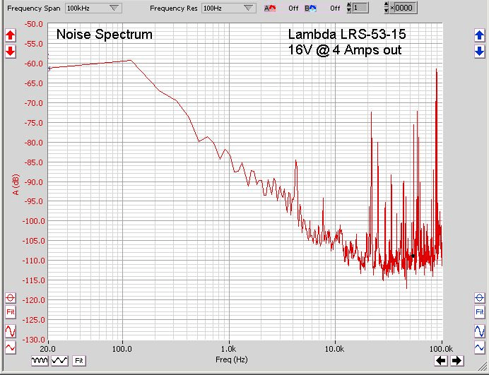
- Noise Coupling Examples: A practical example of SMPS noise impact is seen in measurements. Consider the output noise spectrum of a 150 W switching supply (measured under load): it shows a mostly low noise floor but with a distinct spike around 1.7 kHz and numerous ultrasonic spurs above 10 kHz. These spurious tones (“RF rubbish”) can vary with load and are “spit back” by the SMPS into its output and even into the mains. In an audio system, such spurs could potentially make it into the audible range through intermodulation. Another anecdotal report noted an SMPS producing a ~2 kHz tone and harmonics – likely the result of a particular control loop oscillation. This underscores that SMPS noise is not always a simple high-frequency whine; it can include lower-frequency components if the design isn’t strictly fixed-frequency.
- Mitigation: Good SMPS designs for audio incorporate filters to block both conducted and radiated noise. On the supply output, low-pass filters (inductors or ferrites with capacitors) can attenuate switching spikes to microvolt levels. On the AC input (mains side), common-mode chokes and X/Y capacitors prevent the SMPS from back-injecting noise into the house wiring (which could otherwise travel to other audio components). Still, some noise often remains. One forum post noted that adding an outboard filter to a standard laptop-style SMPS (19 V) improved its noise performance in an audio context – a simple filter module in series reduced the interference. This is essentially an aftermarket way to clean up an SMPS for audio use.
How Everyone can hear at least 30 kHz via Square Waves
Amplify a 10 kHz sine wave. Switch sine to square wave. Stark difference is immediate. The change from sine to square is accomplished by adding onto the sine wave its odd-order harmonics. The 10 kHz sine wave becomes square due to the summing of 10 kHz sine wave, plus 30 kHz sine wave, plus 50 kHz sine wave, plus 70 kHz sine wave, plus 90 kHz sine wave, etc. with each successive odd-order harmonic decreasing in amplitude. This is mathemetically true and easily verified by spectrum analysis.
It’s worth highlighting a counterpoint: not all SMPS are bad for audio. Companies like Benchmark Media have demonstrated that a well-designed SMPS can equal or outperform linear supplies in noise performance. In fact, Benchmark moved entirely to SMPS in their products, stating “linear supplies are too noisy” due to magnetic hum, whereas “a well-designed switching power supply can be much quieter”. The key is well-designed. Benchmark’s supplies switch at ultrasonic frequencies and are heavily filtered; the result is no audible hum and negligible ripple or RF interference at the outputs. They argue that linear supplies, with their big 50/60 Hz transformers, actually limit the noise floor of amplifiers because of magnetic coupling of mains hum. In their view, the high-frequency noise of SMPS is easier to suppress (with shielding and filtering) than the low-frequency fields of a transformer which permeate the chassis. Thus, modern SMPS used in high-end audio (when executed correctly) need not degrade sound at all; on the contrary, they can eliminate mains hum issues entirely.
In summary, SMPS bring tremendous benefits in size and efficiency, but designers must tackle their broadband noise emissions. Audible and ultrasonic artifacts of switching can wreak havoc on sensitive audio circuits if left unchecked. Through proper design – using high switching frequencies, synchronization, filtering, shielding, and sometimes post-regulation – SMPS can be made effectively transparent to the listening experience, as evidenced by many battery-powered and SMPS-powered audiophile devices that achieve vanishingly low noise and distortion. The older myth that “SMPS are always noisy in audio” has been overturned by such examples. Nonetheless, integrating an SMPS demands careful electromagnetic compatibility (EMC) engineering to ensure that what is out-of-band stays out-of-mind (and ear).
Transformer Hum and Mains Interaction
Linear power supplies rely on mains-frequency transformers, which introduce their own quirks. Transformer hum is a two-fold issue: audible acoustic hum from the transformer itself, and electromagnetic hum coupled into audio circuits from the transformer’s field.
- Acoustic Hum (Mechanical): Transformers can emit a low buzz or hum at 50/60 Hz (and its harmonics) due to magnetostriction – the core’s laminations physically vibrate as they magnetize and demagnetize each AC cycle. This hum can often be heard coming directly from the amplifier or power conditioner case. High-quality transformers, especially toroidal types, are usually quieter than cheap laminated ones, but toroids can hum too if there’s any DC offset on the mains. DC on the AC line (caused by asymmetric loads elsewhere on the grid) can push a toroidal core into slight saturation each half-cycle, dramatically increasing magnetostriction buzz. Audiophiles sometimes employ DC blocker circuits on the mains input to eliminate this cause of mechanical hum. Mechanical hum doesn’t directly get into the audio signal electrically, but it’s a nuisance that adds to the noise floor of the listening environment. Good mounting (rubber grommets) and potting can reduce chassis vibration from transformers.
- Electrical Hum Coupling: The transformer’s alternating magnetic field can induce currents in nearby circuitry, which then show up as hum in the audio. This is a form of interference: essentially the transformer is a big inductor broadcasting a 50/60 Hz field. Sensitive high-impedance circuits (phono stages, microphone preamps, tone control circuits) are especially vulnerable. If such circuits are physically too close to the power transformer or oriented improperly, they’ll pick up hum. This is why physical layout in audio equipment matters: often one sees small-signal PCBs placed far from the power transformer, or oriented at right angles to minimize flux pickup, and sometimes enclosed in mu-metal shields. Toroidal transformers have a more contained field than EI core transformers – one of their advantages is much lower external stray flux. However, toroids have other trade-offs (notably, they can transmit high-frequency line noise more readily, discussed below). EI cores, while emitting more stray field, have the advantage of a smaller bandwidth for noise – they inherently filter high-frequency interference from mains better than toroids. In practice, to avoid hum coupling, designers will sometimes choose toroids for their compactness and low stray field. In very sensitive applications, an external power supply chassis might be used, keeping the transformer completely away from the audio circuitry (for instance, some preamps and DACs use outboard linear power units). In professional gear, toroids or well-shielded EI transformers are used, and the chassis itself may be steel to help contain magnetic fields.
- Mains Quality and Interaction: The AC mains supply can carry various unwanted components: voltage fluctuations, high harmonic distortion (from heavy industrial loads), or RF interference (from motors, light dimmers, etc.). A simple transformer will pass any high-frequency noise capacitively from primary to secondary to some extent. Toroidal transformers, due to their construction (often a single-layer winding all around), have higher inter-winding capacitance, hence they can couple more high-frequency noise from the mains into the secondary than an equivalent EI transformer. EI transformers, with separated windings, have a natural low-pass effect, attenuating high-frequency hash. So there is a trade-off: Toroidal vs EI – toroids give less 50 Hz hum field, but more HF mains noise; EI gives more hum field, but less HF coupling. Many high-end designs favor toroids for the field reasons and then add line filtering to handle the HF noise. For example, an X-capacitor across the mains and common-mode choke can shunt away RF garbage. Some audio power conditioners deliberately use a series inductor or an isolation transformer to further filter mains-borne noise. Additionally, mains voltage sag can affect unregulated audio gear (e.g., an amplifier might lose a bit of power output when the mains is 5% low). Regulated supplies, as noted, compensate for that. From a sound-quality perspective, minor mains sag usually isn’t audible except at the extreme, but heavy mains distortion (flat-topped waves) could increase transformer heating and possibly acoustic hum.
In professional settings, maintaining consistent mains power (sometimes via power regenerators or at least conditioners) can ensure each performance sounds the same, with no unexpected hum. In consumer hi-fi, this is why some invest in power conditioners or regenerator units – to reduce transformer hum and noise coupling. However, the efficacy of expensive power conditioners can vary; well-designed audio gear already includes decent filtering.
To summarize, transformers are the heart of linear supplies but bring along mains-frequency artifacts. Mechanical hum from transformers can be mitigated but not always entirely eliminated. Electromagnetic hum can be controlled by distance, shielding, and orientation. The interaction with mains means that what comes in from the wall (be it pure sine or distorted muck) will in some fashion come out of the speakers if the supply and circuit don’t reject it. The goal is to ensure that only clean DC reaches the circuits, and that the transformer’s presence is “felt” as little as possible in the audio. Designers strive for an inaudible noise floor – typically hum at –100 dB or below – and a lot of that depends on smart transformer implementation.
Ground Loops and Audio Clarity
Ground loops are a notorious cause of hum and noise in audio systems. They occur when there are multiple ground return paths between different pieces of equipment, causing small AC currents to flow through the interconnect grounds. These currents introduce a voltage drop (per Ohm’s law) that adds directly to the audio signal reference – manifesting as hum, buzz, or interference. In terms of sound quality, ground loop issues can drastically reduce the clarity of a system by raising the noise floor with a constant hum or hash.
- What is a Ground Loop? Imagine two audio components (say a preamp and a power amp) each plugged into AC mains at different outlets. They are connected by an RCA cable (which provides an audio signal and ground reference). Ideally, all grounds would be at the same potential (zero volts). But if the two outlets have slightly different ground potentials or there is current flowing in the building ground, a small voltage may exist between the chassis of the preamp and power amp. The cable’s ground wire then carries a current to equalize them. This creates a loop: component A -> interconnect ground -> component B -> mains ground wiring -> back to component A. The loop can pick up interference like an antenna (especially 50/60 Hz from any magnetic fields), or the ground current itself can modulate the audio reference. The result: a hum at 50/60 Hz (and often 100/120 Hz buzz) in the audio. Ground loops are particularly pernicious because the user often has no idea why their system is humming – it’s due to wiring practices and ground topology, not a “defect” per se. In analog connections, unbalanced RCA cables are most prone to ground loop hum because the shield is the audio ground. Balanced connections (XLR) largely avoid this by using differential signaling (the shield is not the reference for the audio signal, ideally).
- Effect on Audio Clarity: A strong ground loop hum can be on the order of millivolts or more injected into the signal path – easily audible and often around 60 dB or more below signal level, which is very intrusive. Even a mild hum at –80 or –90 dB can be perceptible in quiet passages as a faint buzz. This constant noise severely masks low-level details in music. Our ears have a masking threshold – a hum in the bass region can cover up quiet details that share the same frequency region or its harmonics. Moreover, even if inaudible as a distinct hum, ground loop currents can cause subtle intermodulation with the signal in nonlinear circuits, theoretically affecting clarity. Usually, however, it’s the obvious noise that’s the issue. Ground loops don’t typically affect distortion of the wanted signal; they just superimpose unwanted noise. So the main degradation is a loss of dynamic range – the “silence” is no longer truly silent.
- Solutions and Design Strategies: The cure for ground loops is to break the offending loop or prevent the conditions that create it. Pro audio gear uses balanced inputs/outputs specifically to combat ground loop issues between equipment – any induced hum becomes a common-mode signal that gets rejected by the differential input. In consumer gear, which often uses unbalanced connections, manufacturers sometimes add ground-lift switches or isolation transformers on outputs to eliminate loops. Within a single device, careful star grounding (a single ground point where all returns meet) is used so that no ground currents flow through sensitive reference points. Also, keeping analog signal ground separate from chassis safety ground except at one point helps. If a ground loop is between two devices on different power circuits, plugging them into the same outlet (same ground reference) often fixes it. Sometimes simply reversing a two-prong plug (for devices without polarized plugs) can reduce a ground loop by shifting how stray capacitances to ground are arranged – though this is trial and error.
For an end-user, a quick fix is using an isolating transformer or ground loop isolator in the audio interconnect – basically breaking the DC ground path while letting audio AC through (via a small coupling transformer). Another method is to ensure all equipment shares a common ground point (e.g. a single power strip) so no large ground potential differences exist. It’s also important to ensure cable shielding is done right: in some cases, double-shielded cables connect the shield at one end only (telescoping ground) to avoid loops, but this is more in custom scenarios.
- Ground Loops within a PCB/Chassis: Ground loops aren’t just an external interconnect issue; they can occur on the circuit board too. If high charging currents from the power supply capacitors flow through a ground trace that also is the reference for a low-level stage, the resistance of the trace can impose a 100 Hz ripple voltage on that stage’s ground. That creates a hum in the output. This is why power electronics and signal electronics grounds are usually separated and then joined at a single point (star ground). The “star” ensures that high current loops (like charging pulses from rectifier to cap return) stay local and don’t flow through the sensitive signal ground reference. Proper PCB layout and grounding can make the difference between an amplifier with 0.5 mV output hum and one with 5 mV hum.
In essence, ground loops rob audio of clarity by injecting hum. They highlight that a power supply is more than just “DC voltages” – it also encompasses the return paths and grounding scheme. A silent ground (i.e., one with no circulating currents or interference) is as important as a clean positive voltage rail. Good equipment design plus correct system setup will avoid ground loops. But when they do occur, the impact on sound quality is immediately apparent: low-level detail and transparency are drowned in a low-frequency fog. Therefore, engineers treat grounding with as much importance as the active circuitry, employing both measures in design and guidelines for users to ensure the purity of the audio isn’t compromised by something as unglamorous as a ground loop.
Electromagnetic Interplay in Layout and Components
The physical implementation of an audio circuit – PCB trace geometry, component placement, wiring, etc. – can significantly influence the electromagnetic interactions that ultimately shape the sound. Several micro-level factors come into play:
- PCB Trace Geometry & Layout: The way power and signal traces are routed can make the difference between a quiet design and one plagued by crosstalk or oscillations. For instance, a long trace carrying a fast-changing current (like a digital clock or a class D switching node) can inductively or capacitively couple into a high-impedance audio input trace if they run in parallel. Good layout practice is to keep high-level, high-speed, and sensitive nodes separated and use ground planes or shields as barriers. Star routing of power (to avoid ground loops as mentioned) and twisting of paired traces (to cancel out magnetic fields) are common techniques. PCB traces also have resistance and inductance – a long thin trace feeding an op-amp’s supply might drop voltage during transients or ring with decoupling capacitors. Thus, near every op amp or analog IC, designers place bypass capacitors right at the power pins to provide a local low-impedance source for fast currents, preventing the trace inductance from causing a voltage dip or high-frequency noise. If such decoupling is omitted or placed far away, op amps can become unstable or inject supply noise into the signal. In sum, PCB layout is almost as much an art as circuit design in high-end audio; many “mysteries” of one design sounding different from another boil down to layout-induced noise or interference differences.
- Op-Amp Internals (PSRR and EMI susceptibility): Op-amps and other active devices have finite power supply rejection (PSRR) – meaning some portion of supply fluctuations will appear at the output. PSRR typically worsens with frequency. For example, an op-amp might have 120 dB PSRR at DC (virtually no hum gets through) but only 60 dB at 100 kHz, meaning if there’s 100 mV of 100 kHz noise on its supply, 0.1 mV could appear at the output. 0.1 mV is –80 dBV, which might be just at the edge of audibility or at least measurable. Thus, high-frequency supply noise that sneaks past decoupling can break into the audio band via op-amp PSRR limitations. Modern op-amps designed for audio often have excellent PSRR and also incorporate input EMI filters because the input stage can rectify RF (as mentioned). TI notes that op-amp input pins are usually the most EMI-sensitive node – strong RF can shift the input offset or bias currents. This is why some op amps marketed for audio (or automotive, where EMI is everywhere) have built-in RFI filters. If not, external small capacitors or RF chokes might be added at inputs to shunt RF to ground. Another internal consideration: slew rate and output drive – if a layout causes an op-amp to oscillate (say at a few MHz) due to output capacitance or feedback impedance, that oscillation can modulate the audio or cause distortion. Often, squashing these parasitic oscillations (with snubber networks or better layout) yields a cleaner, more “open” sound once the ultrasonic garbage is gone.
- Potentiometers and Passive Components: Even passive parts can exhibit electromagnetic and mechanical interactions. A potentiometer (volume control) is essentially a resistor with a movable wiper – at certain settings, the source impedance seen by the next stage is the parallel of two resistances, which could be a few kΩ. This node can be high-impedance and thus susceptible to picking up hum or RF. That’s why in high-end gear, volume pots are often placed at low-impedance points (e.g., in a feedback network) or followed by a low impedance buffer, so that the pot’s wiper isn’t a big antenna. The material of the potentiometer track (carbon vs conductive plastic vs cermet) can affect noise and even microphonics. Some cheap carbon pots can become microphonic – if you tap them, you hear it in the speakers – due to the carbon grains moving slightly (this is a triboelectric effect or mechanical coupling). Conductive plastic tends to be less noisy and less microphonic. Wirewound pots (common in power rheostats) would introduce inductance (not great for audio frequency response) and can have a wiper noise if the wire spacing is not fine. For critical low-noise applications, stepped attenuators (an array of resistors switched by a rotary switch) are used to get essentially noise-free, precision volume control. Even the wiper contact quality matters; a scratchy pot introduces crackles (which are bursts of noise and DC shifts). So while potentiometer choice is more about noise and reliability than sound “character,” a bad pot can certainly degrade perceived sound quality (no one enjoys crackle or imbalance between channels).
- Transformer Windings and Layout: We touched on transformer electromagnetic fields earlier. Within a power transformer, the arrangement of windings can influence the inter-winding capacitance and leakage inductance. Some high-end transformers include an electrostatic shield between primary and secondary – a thin copper foil connected to ground – to intercept capacitive coupling of HF noise from primary to secondary. This reduces the noise transmitted to the audio circuit side (common in medical or instrumentation transformers, but also used in audio). The winding geometry can also affect regulation (a tightly coupled secondary regulates better under load but passes more HF). Some audiophile transformers are specified for “low mechanical noise” and “low electrical noise,” meaning they are designed to minimize both hum and HF coupling. Furthermore, in an amplifier with multiple secondary windings (for example separate secondaries for left and right channels, or for high-voltage vs low-voltage sections), how those windings are run and twisted can affect cross-coupling. If the secondary leads going to one channel’s rectifier are routed next to the other channel’s leads, you could get some magnetic coupling between channels’ supply pulses – a form of crosstalk. Keeping channel power feeds separated helps preserve the isolation between channels (improving stereo separation in terms of power supply interaction).
- System Impedance and Resonances: Every interconnect in the power delivery network (including PCB traces, wires, transformer, capacitors) forms an RLC network. These networks can have resonant peaks. For example, a long DC supply rail with a large capacitor at one end and an active load at the other can ring at some frequency when a transient occurs. If the PCB trace inductance and cap ESR conspire, you might get a little 50 kHz ringing on each transient. This is normally damped out by resistances in the circuit, but if not, such ringing might inject ultrasonic tones. Similarly, a bypass capacitor with very low ESR can form an LC tank with the supply inductance – sometimes adding a tiny series resistor (or using a slightly lossier cap) actually improves stability by damping resonances. Thus, practical design sometimes deviates from idealized “zero impedance at all costs” – a bit of controlled impedance can tame ringing. Op amp internals also have output impedance and feedback loops that must be stable against capacitive loads (like long cables). Adding an isolation resistor at an output can prevent high-frequency oscillation when driving a capacitive cable. If these measures are overlooked, the system could oscillate or ring, affecting sound (often as a harshness or bright distortion due to ultrasonics riding on the signal).
- EMI from Digital Components: In digital audio components (DACs, DSPs, CD transports), you have high-frequency clocks and data lines toggling. Without careful grounding and decoupling, this digital hash can pollute the analog sections. Manufacturers often partition digital and analog ground planes, only joining them at a single point. They also provide separate regulated supplies for analog vs digital sections of a DAC, etc. This prevents digital currents from flowing through analog ground returns and causing noise. An anecdote: early CD players sometimes had issues where the display or CD drive’s noise would couple into the audio outputs, causing faint whines or hash – later designs learned to isolate and filter these better.
In essence, the electromagnetic interplay in audio gear is a multidimensional challenge. PCB geometry determines what is capacitively or inductively coupled to what; component choices (like pot types, op-amp EMI ratings, transformer shielding) determine how resilient the circuit is to interference. High-end audio design often involves iterative tweaking of layout and grounding to chase away every last bit of unwanted interaction. It’s why two amplifiers with the same schematic can sound different: the physical realization matters. The interplay of stray capacitances, inductances, and external fields is complex, but successful designs manage these strays and often turn them to advantage (for example, using a bit of lead inductance as part of an output Zobel network, etc.). Ultimately, minimizing unintended electromagnetic coupling leads to an audio path that reproduces the input signal with greater purity – i.e., better clarity, lower noise, and less distortion.
Capacitive Energy Storage: Impact on Performance and Sound
Capacitors are the workhorses of power supplies, acting as energy reservoirs. Increasing capacitive energy storage – both on the AC line side and the DC output side – can improve supply stiffness but also introduces certain trade-offs. We’ll examine both sides:
- Input Side (Line Side) Capacitors: On the AC mains side, equipment often has EMI/RFI filter capacitors (so-called X and Y caps) but these are small (microfarads or less) and meant for noise suppression, not energy storage. However, some power conditioners or specialized supplies use capacitors or even batteries to provide ride-through for the mains. For instance, a power regenerator might briefly draw from a capacitor bank when the incoming AC dips. In general, large line-side capacitance isn’t common because it would draw spiky currents from the mains (poor power factor). When you rectify AC to DC, the bulk of energy storage is after the rectifier (DC side). That said, a concept of “power factor correction (PFC) capacitors” on mains can store some energy – e.g., motor run capacitors in AC circuits – but in audio, a better approach is active PFC circuits if one wants to draw a sinusoidal current. Some high-end amps have power factor correction front ends which effectively buffer the mains. The subjective benefit could be that the amp is less disturbed by other appliances turning on/off, etc. (This is a complex topic, but one anecdotal example: if an audio system draws huge current peaks on each mains cycle due to big caps, it can cause the mains voltage in the house to momentarily sag or distort, potentially affecting other gear on the same circuit. With PFC, the current draw is smoother.)
- Output Side (DC Bus) Capacitors: Large reservoir capacitors on the DC rails are crucial in unregulated supplies. They charge up to the peak of the transformer secondary and then supply current while the AC waveform between peaks. The larger the capacitance, the smaller the ripple for a given load. More capacitance also means the rail voltage droops less during a sudden burst of current (because the cap can supply the extra charge). Therefore, increased capacitance generally improves performance: lower ripple (thus lower hum), and better sustained voltage on transients (thus potentially lower distortion on peaks). For example, if an amplifier momentarily demands 5 A for a bass drum kick, a larger cap bank will supply that without the rail voltage falling as much, whereas a smaller cap might allow a 5–10% drop that slightly clips or compresses the wave. This is why upgrading power supply capacitors is a common tweak – e.g., going from 10,000 µF to 30,000 µF on each rail. Many report tighter bass and improved dynamics from such an upgrade, which aligns with the objective reduction in sag and ripple. However, there are diminishing returns. Beyond a certain capacitance, the improvements become negligible because the amplifier’s own PSRR and the existing capacitance were already sufficient. Also, extremely large capacitors can have downsides:
- Inrush current: When first powered on, big caps draw a large surge from the transformer to charge. This can stress rectifiers or blow fuses if not managed (hence soft-start circuits or thermistors are used in amps with huge banks).
- Charging pulses: The larger the caps, the shorter and higher amplitude the current pulses from the rectifier become (as the caps stay near full voltage and only top-up at the peaks). These high current pulses can introduce more high-frequency noise and magnetic field pulses inside the chassis, which could potentially couple to audio circuitry. Paradoxically, a moderate amount of ripple current spread over a longer time (with smaller caps) might produce less high-frequency content than very sharp current spikes with huge caps. Usually, this is managed by proper layout (twisting the rectifier-to-capacitor leads, etc.) and is not audible, but it’s a consideration.
- Stability: In regulator circuits, too much output capacitance can sometimes make the regulator oscillate (if the cap’s ESR is too low or the value outside stable range). In unregulated amps, adding massive capacitance can shift the pole of the supply impedance to a very low frequency, which could – in theory – make an amplifier more prone to motorboating if the front-end decoupling isn’t similarly beefed up. In practice, designers usually scale decoupling throughout (big main caps and also adequate stage isolation).
- Energy Storage and Dynamics: Subjectively, having greater energy storage gives the impression of an amplifier that is unflappable. For example, an amp with undersized caps might audibly falter on deep bass at high volume – the bass could sound a bit muddy or the amp could even distort slightly as the rails dip. With ample capacitance, the amp delivers the bass hit with full voltage, and the listener perceives it as tighter and more impactful. There is also the matter of damping factor consistency: in a class AB amplifier, the power supply capacitance contributes to the output impedance at low frequencies. If the rail sags under load, the effective output impedance seen by the speaker increases (damping factor decreases), which could affect bass control. More capacitance -> less sag -> more constant damping factor across transients.
- Supercapacitors and Novel Approaches: In the last decade or two, there have been experiments with supercapacitors (farads of capacitance) in audio power supplies. Some DIYers and boutique manufacturers have tried using supercaps to essentially act as a near-battery for the amp, keeping the supply rock-steady. While these can supply huge bursts of current, their voltage ratings are low, so they often need to be put in series for higher-voltage rails, and they can be expensive and require management (balancing circuits). The audible gains beyond what conventional large electrolytics provide are debatable. Often the bottleneck is elsewhere (the transformer VA, or the amp’s thermal limits, etc.) rather than the storage.
- Line-Side Storage (Power Conditioners): Products like UPSs or regenerators sometimes advertise they have energy storage to handle peaks in demand. For example, a power regenerator (which takes AC, converts to DC, then back to a very pure AC) might have a substantial capacitor bank so that when your amp draws a sudden surge, the regenerator supplies it from stored energy rather than drawing a sudden surge from the wall (which could cause a voltage dip). This can be beneficial if your household mains are flaky. Some audiophiles report improved dynamics when using such devices, possibly because the amplifier is then fed by a source with lower source impedance (the regenerator’s output) than the raw wall outlet. Objectively, devices like the PS Audio Power Plant aim to provide a low-impedance AC source. If the mains has impedance (say a few tenths of an ohm from the transformer to your outlet), a big amp drawing current will sag the wall voltage slightly. With a regenerator or conditioner that has internal storage, the AC delivered to the amp stays at full voltage during transients. The difference might only be a volt or two on the rails, but it could separate clipping vs not clipping in extreme cases.
In conclusion, increasing capacitive storage on the DC bus is almost always beneficial up to practical limits – it lowers noise (ripple) and improves load regulation and thus performance. On the AC side, storage is more about power delivery and power factor; while it can help isolate from mains issues, it’s typically implemented via active circuits rather than just a huge capacitor across the mains (which would be unsafe and draw large reactive current). The perceived sound improvements from more capacitance usually align with the technical improvements: tighter bass, better dynamic slam, and stability under heavy load. But once you have “enough” capacitance such that rail sag and ripple are negligible relative to the signal demands, adding more may not further audible improvement. A well-known quote in audio is that “the power supply defines the amplifier’s character” – by ensuring ample energy storage and low impedance, one allows the amplifier circuit to perform at its best without being undermined by supply weaknesses. This is one area where objective and subjective sides generally agree: insufficient power supply capacitance yields audible drawbacks, whereas generous capacitance is a cornerstone of great amplifier performance (hence the often impressive arrays of capacitors in high-end amps).
Boutique Cables and Ultrasonic Signal Integrity
Finally, we turn to a somewhat different but related topic: audio interconnects and speaker cables, especially high-end “boutique” varieties (e.g., Cardas, Monster Cable, AudioQuest, etc.), and how they might relate to ultrasonic frequencies and overall signal integrity. While cables are not part of a power supply, they are part of the signal chain’s passive infrastructure. The question prompt specifically mentions “ultrasonic excitations and signal integrity” in relation to boutique cables, suggesting a focus on how cable design might affect high-frequency behavior that could influence perceived sound.
- Cable Electrical Characteristics: Any cable has resistance (R), inductance (L), and capacitance (C). In the audio band, most decent cables act like near-ideal low-value RLC components. For speaker cables: low resistance is important for damping factor, inductance can cause slight HF roll-off with the speaker’s impedance, and capacitance is usually low enough not to burden the amp – except some exotic cables have very high capacitance which can provoke amplifier instability (ultrasonic oscillation). Indeed, there are cases where certain esoteric speaker cables (often litz or parallel conductors to reduce inductance) had such high capacitance that amplifiers oscillated at ~100 kHz. This would definitely affect sound, causing overheating and distortion. Some cable makers (MIT, for example) include networks to mitigate this, acting as Zobel networks to stabilize impedance. High inductance cables (like some very thin or long cables) might attenuate ultrasonics, but typically that’s negligible in audible range unless the cable is extremely long.
- “Ultrasonic Excitations”: Some boutique cable designs talk about resonance control. For example, Cardas Audio employs a patented “Golden Ratio” strand litz construction. The idea is that by using different strand sizes and spacing in golden ratio proportions, internal resonances in the bundle are spread out rather than coincident, thereby nulling inter-strand resonance. Cardas claims this reduces smearing of transients and preserves detail by avoiding any specific high-Q resonant frequency in the cable. In essence, the cable’s L and C are distributed in a non-uniform way to avoid creating an ultrasonic filter or ringing at a particular frequency. Additionally, Cardas’s “matched propagation” theory posits that if the signal’s propagation velocity in the conductor vs the dielectric are matched, you minimize time-domain smearing – this is geared toward very high frequencies (radio frequencies, really) because in the audio band signals travel near instantaneously in any typical cable (the “smearing” here is more a marketing concept than something that happens at audio frequencies). Nevertheless, these designs are trying to ensure that if any ultrasonic content (like a fast transient or noise beyond audio) passes through, the cable doesn’t introduce ringing or phase shifts that could fold back or affect the audible range. Monster Cable, historically, focused on lower resistance and higher copper purity, etc., but also had concepts like “Time Correct Windings” which were supposed to align the timing of high and low frequency signals (likely referring to skin effect differences). Skin effect (the tendency of HF currents to travel on the conductor surface) is negligible at audio frequencies (skin depth in copper at 20 kHz is about 0.5 mm, so even a thin 0.5 mm strand carries full spectrum almost uniformly). At ultrasonic or RF, skin effect does matter, but whether any content that high is relevant in audio is questionable.
- Signal Integrity in Digital Cables: If we consider digital audio cables (like HDMI, USB, or S/PDIF coax), then signal integrity at high frequency is very much a concern (waveform shape, jitter, etc.). But the question seems more aimed at analog cables in relation to ultrasonic phenomena. One angle: cables can act as antennae for RF interference. A poorly shielded interconnect might pick up radio signals (which are ultrasonic relative to audio). Indeed, classic examples include audio systems picking up AM radio due to cables and circuits inadvertently demodulating it. Boutique cables often have enhanced shielding or braided designs to reduce RFI ingress. For instance, some high-end interconnects use multiple shields and even RF absorption materials, claiming a quieter background. If an audio cable picks up ultrasonic interference (say from a nearby Wi-Fi router or cellphone), that interference might not be heard directly, but could intermodulate in the amplifier input to produce noise. A cable that better rejects that (through shielding or twisting) could legitimately result in cleaner sound in an RF-rich environment.
- Evidence of Audible Differences: The topic of cable sound is highly controversial. Objectively, in short runs and with competent equipment, most standard cables (of proper gauge and shielding) do not introduce frequency response or distortion deviations within the audio band that are anywhere near human thresholds. However, the aforementioned AES paper by Kunchur (2021) provided evidence that under very careful conditions, listeners could distinguish between two analog interconnects. The exact technical differences between those cables weren’t fully disclosed in the abstract, but one can surmise there might have been slight differences in frequency response at the extremes or in how they handled ultrasonic content. It might be that one cable had higher capacitance, rolling off ultrasonics or causing slight phase shift at 20 kHz, and the other did not – and perhaps listeners detected a subtle difference in “air” or spatial detail. Psychoacoustically, humans are not very sensitive to absolute phase, but very high frequency content (even above 20 kHz) could affect timbre through intermodulation with audible frequencies (if our ear or equipment creates that). So if one cable allowed more ultrasonic junk through, it might worsen the sound in a high-RF environment by letting the amplifier deal with it. Another might filter it benignly. Boutique claims vs reality: Many boutique cable claims venture into quasi-mystical territory (golden ratio, crystal alignment, “quantum” treatments). While the scientific basis is often weak, some of these design choices essentially ensure the cable is an excellent transmission line with wide bandwidth and minimal resonance. For analog audio, having a –3 dB point at, say, 2 MHz instead of 200 kHz is irrelevant to 20 kHz signals, unless something in the chain is interacting at those frequencies. For example, an amplifier with very high input impedance and feedback could oscillate at 1 MHz if the cable and source impedance create the right condition. A cable that by luck or design presents a load that avoids that oscillation might “sound” better simply by removing an ultrasonic oscillation that the other cable induced. These are very system-dependent situations. On the flip side, some exotic cables with built-in networks (Zobel or resonance traps) might intentionally roll off ultrasonics to ensure stability or to tailor the sound. This is more common in speaker cables (e.g., some have a characteristic impedance network to avoid reflections in the MHz range – not that audio needs that, but it could damp out an amp’s tendency to ring).
- Ultrasonic Excitation of Cables: A curious phenomenon is microphonic cables. High capacitance cables can physically expand/contract under voltage (electrostatic forces) or vibrate under current (electromagnetic forces). In extreme cases, speaker cables can “sing” (emit sound) if carrying very high power ultrasonic signals – this is more a lab curiosity (it’s been observed in RF transmitters with open-wire lines that the lines can whistle). In audio, not really an issue. However, cables can be microphonic – a high-impedance cable (like a guitar cable into a tube amp grid) can pick up mechanical vibration and generate voltage (capacitor microphone effect). Interconnects in hi-fi (low impedance source, high impedance input) could potentially do this a bit. Some audiophile cables are quite stiff or use damping material to reduce vibrations, claiming that reduces microphonic effect that could modulate the signal. This is more plausible in tube gear with high impedance circuits.
In conclusion, boutique cables aim to maintain signal integrity often far beyond the audible range, on the premise that preserving waveform purity (no matter how ultrafast) results in better sound. While the objective impacts of most such designs in the audio band are extremely subtle (fractions of a dB at 20 kHz, or microseconds of timing difference), the subjective reports can be strong – indicating either that listeners hear something we don’t readily measure, or psychological bias, or system-specific interactions. There is some evidence that under certain conditions cables can be audibly distinguished, suggesting the conservative engineering approach is to ensure cables don’t introduce any anomalies even at frequencies well beyond hearing. Ensuring low resistance, moderate inductance, low capacitance, and good shielding addresses most of this. As one cable manufacturer’s literature noted, using ultra-pure copper and air insulation further reduces dielectric losses and “cable resonance”, potentially contributing to that last nth of a percent of performance.
From a scientific perspective, as long as a cable’s impedance properties are benign (no resonant peaks, flat frequency transmission through the relevant range), it shouldn’t create ultrasonic problems. But a poorly chosen cable (like a very high capacitance type on a marginally stable amp) can certainly cause ultrasonic oscillation and thus audible degradation. Therefore, in designing an audio system (including cables), one must consider the interaction of cable impedance with the source and load. Boutique cables often ensure these parameters are well controlled (sometimes at the cost of being very expensive ways to essentially do what a basic well-made cable could do). In any case, ultrasonic interference or resonance is an area where cabling and power supply meet the signal path: keep everything well-behaved beyond the audible band, and the result will be objectively clean and subjectively transparent sound.
Conclusion
Power supply design is integral to audio performance – it is the unseen backbone that can either support or undermine the fidelity of an audio system. Objectively, a well-designed supply minimizes its own influence: it provides steady DC rails with low noise, low impedance, and no unwelcome oscillations or interactions, thereby allowing the audio circuitry to perform optimally (with lowest distortion, widest bandwidth, and highest dynamic range). We’ve seen how factors like regulation, capacitive storage, grounding, and layout each contribute to measurable outcomes such as THD, TIM, slew rate, noise floor, hum, and crosstalk. Subjectively, listeners often describe the effects of power supply improvements in terms like clarity, punch, soundstage, or bass tightness – essentially the audible manifestations of reduced noise and distortion. While some audiophile claims can be exaggerated, many align with real electrical improvements.
A strict regulator can lower hum and keep an amplifier linear under stress, but designers must ensure it’s fast and stable enough not to introduce new issues. A generous unregulated supply with big capacitors can yield nearly the same benefit, with perhaps a bit more raw dynamic headroom at the cost of more weight and heat. Switch-mode supplies offer a new paradigm – virtually eliminating mains hum but requiring careful suppression of switching noise; done right, they can be as good or better than linear supplies in performance. Issues like motorboating remind us that holistic design (considering the interaction of stages through the supply) is crucial – an audio device is an ecosystem, not isolated blocks. Ground loops teach that even outside the device, how we interconnect systems power-wise can inject noise, meaning high-level design (providing balanced connections or ground isolation) is just as important for real-world performance.
We also explored how every piece, down to PCB traces and component choices, has an electromagnetic footprint. Decades of audio engineering have established best practices: star grounds, short decoupling paths, separation of analog/digital, shielding of transformers, etc., to mitigate interference. Adhering to these yields the transparent results we desire – where the power supply quietly does its job and the listener never notices it. Conversely, any lapse (say an insufficient decoupling cap or a loop in the ground) can subtly or not-so-subtly color the sound.
In the past 10 years, research and practice have continued to refine these understandings. We have listening tests correlating regulator output impedance with perceived sound, and findings that indeed “the last 5%” in power supply performance can be audible to discerning listeners. On the other hand, we also have evidence that many supposed differences disappear under controlled conditions, reinforcing that human perception can be biased and that objective rigor is needed. When a supply is truly well engineered, its contribution to sound quality should be neutral – it should simply enable the circuit to do its job without adding a signature. The ultimate compliment to a power supply in audio might be that it’s never noticed at all.
In summary, power supply design wields a profound influence over audio gear performance. From eliminating hum and preventing distortion, to possibly shaping the subjective character of the sound, it’s a field where electrical engineering meets psychoacoustics. By marrying solid theoretical design (low noise, low impedance, proper filtering) with practical considerations (grounding schemes, component layout, even cable interactions), designers achieve the dual goal: superb measured specs and musical sound quality. As the references and examples show, the devil is in the details – and in audio, those details span from the wall plug all the way to the speaker terminals (and every link in between, power and signal). Keeping those links robust and transparent is the key to high-fidelity reproduction.
Ultimately, whether it’s a massive linear supply with banks of capacitors, a high-tech SMPS, or an ultra-low-noise regulator for a DAC, the principles remain: provide the audio circuitry with as ideal a source of power as possible – then sit back and enjoy the music, free from power-induced perturbations. When the power supply is right, the silence is silent, the transients are crisp, the imaging is stable, and the sound is true to the source – which is the hallmark of high-end audio design.
References (informative sources cited throughout):
- Self, Douglas. “Audio amplifier power supply design – Part 1: Power supply types & transformer considerations.” EE Times, 2025.
- Linear Audio (J. Walton et al.). “A comparative overview of power supply regulator designs with listening tests.” Linear Audio Vol.4, ca.2013.
- Wikipedia – Motorboating (electronics) (causes and solutions for low-frequency oscillation in audio).
- Audiophile Style Forum, “Is it possible for a power supply to affect sound quality?” (StephenJK & others, June 2020) – discussion on low-impedance supplies and noise.
- Benchmark Media (J. Siau). “Audio Myth – Switching Power Supplies are Noisy.” Benchmark Application Notes, May 2016 – explains hum from linear transformers vs well-designed SMPS.
- Cardas Audio Tech Notes – Golden Ratio Stranding and Matched Propagation (Cardas Clear cable info).
- Kunchur, M., “Cable Pathways Between Audio Components Can Affect Perceived Sound Quality.” JAES, Vol. 69 No.6, 2021.
- diyAudio Forum discussions: EI vs Toroidal transformers, SMPS noise measurements, etc. (various dates).
- Sound Devices Tech Note – “Tackling Ground Loop Noise” (n.d.) and Sound On Sound – “Understanding & Solving Ground Loops” (H. White, 2004).
- Leach, Marshall. “Build a Low-TIM Amplifier” Audio Magazine (1976), and Leach Amp website – background on TIM distortion.